From S.H.O.
In Phase 3…
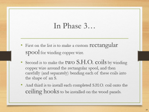
• First on the list is to make a custom rectangular spool for winding copper wire.
• Second is to make the two S.H.O. coils by winding copper wire around the rectangular spool, and then carefully (and separately) bending each of these coils into the shape of an S.
• And third is to install each completed S.H.O. coil onto the ceiling hooks to be installed on the wood panels.
Magnet wires
(Top)
| Magnet Wires
(Phase 3 Parts)
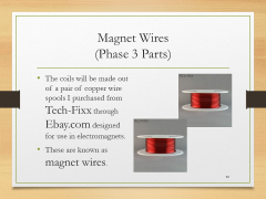
• The coils will be made out of a pair of copper wire spools I purchased from Tech-Fixx through Ebay.com designed for use in electromagnets.
• These are known as magnet wires. |
| Magnet Wires
(Phase 3 Parts)
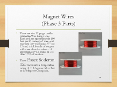
• These are size 12 gauge on the American Wire Gauge scale. Each coil has approximately 100 feet (or 30 meters) of wire, and together they will form a ½” (or 13 mm) thick bundle of copper with a combined resistance of approximately 0.3 ohms, or less than 1/3rd of an ohm.
• These Essex Soderon 155 wires have a temperature rating of 311 degrees Fahrenheit or 155 degrees Centigrade. |
|
Re-spooling
(Top)
| Hole Diameter
(Compatibility)
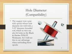
• The magnet wire came with spools whose hole diameter fits well with a 5/8” diameter threaded rod, which in turn can also fit holes in the Black & Decker WM125 Workmate. So I will use this to my advantage when unwinding these spools. |
| S.H.O. Drive
(Design)
• Unlike any other drive motor in on the market today, the S.H.O. Drive will possess a pair of rectangular conductive windings each folded in such a way to look like the letter S, the letter H, or the letter O, depending how on viewed. |
| Custom Spool
(Assembly)
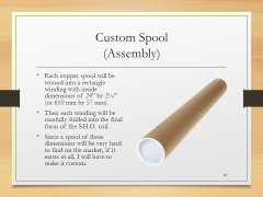
• Each copper spool will be wound into a rectangle winding with inside dimensions of 24” by 2¼” (or 610 mm by 57 mm).
• Then each winding will be carefully folded into the final form of the S.H.O. coil.
• Since a spool of these dimensions will be very hard to find on the market, if it exists at all, I will have to make it custom. |
| Mailing Tube
(Equipment)
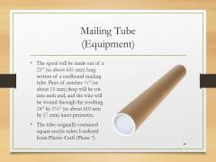
• The spool will be made out of a 25” (or about 635 mm) long section of a cardboard mailing tube. Pairs of notches ½” (or about 13 mm) deep will be cut into each end, and the wire will be wound through the resulting 24” by 2¼” (or about 610 mm by 57 mm) inner perimeter.
• The tube originally contained square acrylic tubes I ordered from Plastic-Craft (Phase 7). |
|
Bending the coil
(Top)
| Nylon Fasteners
(Phase 3 Tools)
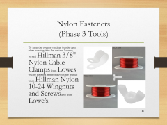
• To keep the copper winding bundle tight when curving it to the desired S-curve, several Hillman 3/8" Nylon Cable Clamps from Lowes will be fastened temporarily on the bundle using Hillman Nylon 10-24 Wingnuts and Screws also from Lowe’s. |
| Curved Ruler
(Tools)
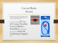
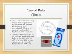
• I must ensure that the long side of the 24”x2¼” conductive winding has the correct form of S curve.
• So I will be using a 24”(or 610 mm) Flexible Curved Ruler by Staedtler that I purchased from inside an Artist & Craftsman Supply store. |
| S.H.O. Coils
(Assembly)
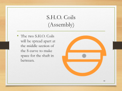
• The two S.H.O. Coils will be spread apart at the middle section of the S curve to make space for the shaft in between. |
| Curved Ruler
(Tools)
• The 12 American Wire Gauge copper wire is significantly rigid by itself, and it will be even more so when approximately 22 turns of such wire are bundled together in each S.H.O. coil
• Therefore I have used the 24” (or 610 mm) Flexible Curved Ruler by Staedtler, which is stiff in its own right, to trace various models for the S Curve of the S.H.O. Coils. |
| Visualis Electromagnetism
(Software)
• To digitally render the optimized shape for the S.H.O. coils, I used Microsoft Excel to overlay an XY plot chart over a scan of a desired model for the S Curve and adjusted the X and Y values to match the curve.
• Then using Excel Functions, I produced the code for a
•.viz file which I imported into Visualis Electromagnetism (from visualis-physics.com). |
| Tubing Bender
(Phase 3 Tools)
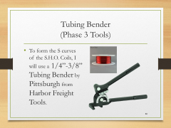
• To form the S curves of the S.H.O. Coils, I will use a 1/4”-3/8” Tubing Bender by Pittsburgh from Harbor Freight Tools. |
| Tubing Bender
(Phase 3 Tools)
• To hold the tubing bender to the workbench, I will use 3 in. Industrial C-Clamps that I obtained from a Harbor Freight Tools store. |
|
Ceiling hooks
(Top)
| Ceiling Hooks
(Phase 3 Parts)
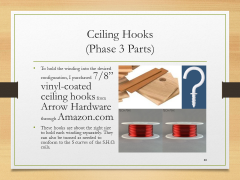
• To hold the winding into the desired configuration, I purchased 7/8” vinyl-coated ceiling hooks from Arrow Hardware through Amazon.com.
• These hooks are about the right size to hold each winding separately. They can also be turned as needed to conform to the S curves of the S.H.O. coils. |
| Wood Panels
(Disassembly)
• Before I can drill pilot holes onto the wood panels for the ceiling hooks, I must unscrew the hinges from the wood panels, set aside the wood base blocks, and then pull out the panels off the bearings. |
| Ceiling hooks
(Assembly)
• To drill pilot holes for the ceiling hooks, I will again use the 18 Volt Cordless 3/8 in. Drill by Drill Master that I purchased inside a Harbor Freight Tools store.- |
| Bundle Diameter
(Compatibility)
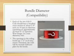
• Each of the two S.H.O. Coils should have a bundled cross-section of about 3/8” inch (or 10 mm) in diameter consisting of approximately 22 turns of 12 American Wire Gauge (or 2 mm diameter) wire.
• The openings in the ceiling hooks are 1/3” (or 8 mm) across. Therefore, the coils will be securely held into place by the hooks. |
| Electrical Tape
(Parts)
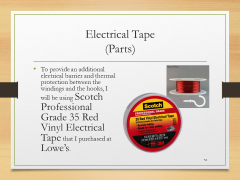
• To provide an additional electrical barrier and thermal protection between the windings and the hooks, I will be using Scotch Professional Grade 35 Red Vinyl Electrical Tape that I purchased at Lowe’s. |
| Drill Bits
(Phase 3 Tools)
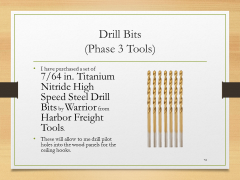
• I have purchased a set of 7/64 in. Titanium Nitride High Speed Steel Drill Bits by Warrior from Harbor Freight Tools.
• These will allow to me drill pilot holes into the wood panels for the ceiling hooks. |
|
Connecting the S.H.O. Coils
(Top)
| S.H.O. Coils
(Assembly)
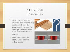
• After I make the S.H.O coils and install the ceiling hooks, I will slide the wood panels back on the bearings, and then screw them back onto the base hinges.
• Then I will insert the S.H.O. Coils into the ceiling hooks. |
| Wire Connector & Sandpaper
(Phase 3 Parts & Tools)
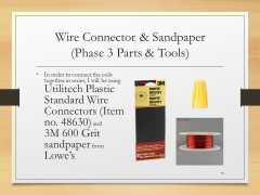
• In order to connect the coils together in series, I will be using Utilitech Plastic Standard Wire Connectors (Item no. 48630) and 3M 600 Grit sandpaper from Lowe’s. |
|
April 2016 Presentation
(Top)
| I
|

Introduction
Summary of measuring devices, back up and safety equipment, and camcorder (+accessories)
|
| 1
|

Phase 1
Holes, brass hinges, square nuts
|
| 2
|

Phase 2
Neodymium magnets and bearings
|
| 3
|
Phase 3
Spool, coils, and ceiling hooks
|
| 4
|
Phase 4
No hidden batteries, increase rigidity, hex nuts, terminal rings, toggle switch, fan blades, and extended test run
|
| 5
|

Phase 5
Heavy duty basket, S.H.O. Drive insertion, secure meters, and portable extended test run
|
| 6
|
Phase 6
Square tote, plastic spools, protective edge trim, and enclosed extended test run
|
| 7
|
Phase 7
Prepare elevated test platform, outdoor test setup, camcorder hookup to portable power, and outdoor extended test run
|
Site map
HQ ● Glossary ● April 2016 Presentation


