From S.H.O.
In Phase 2
• First on the list is to assemble a rotor of neodymium magnets onto the shaft.
• Second on the list is to insert the rotor through the bearings securely into the disassembled wooden panels.
• And third is to reattach the wood panels back onto the wood base blocks.
Neodymium magnets
(Top)
| Neodymium Magnets
(Phase 2 Parts)
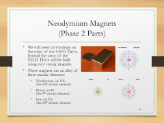
• We will need no windings on the rotor of the S.H.O. Drive. Instead the rotor of the S.H.O. Drive will be built using very strong magnets.
• These magnets are an alloy of three atomic elements:
• Neodymium (or Nd) (the 60th atomic element)
• Boron (or B) (the 5th atomic element)
• Iron (or Fe) (the 26th atomic element) |
| Neodymium Magnets
(Phase 2 Parts)
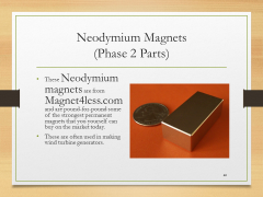
• These Neodymium magnets are from Magnet4less.com and are pound-for-pound some of the strongest permanent magnets that you yourself can buy on the market today.
• These are often used in making wind turbine generators. |
| Neodymium Magnets
(Phase 2 Parts)
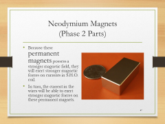
• Because these permanent magnets possess a stronger magnetic field, they will exert stronger magnetic forces on currents in S.H.O. coil.
• In turn, the current in the wires will be able to exert stronger magnetic forces on these permanent magnets. |
|
Assembling the magnet rotor stack
(Top)
| Securing the Shaft
(Protocols)
• To secure the shaft into place, I will thread some extra square nuts temporarily onto the shaft and clamp them down onto the Black & Decker Workmate with the Bessey XM7 3-Inch Metal Spring Clamp that I obtained from inside a Woodcraft store. |
| Magnetic Pole Detector
(Measuring Equipment)
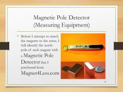
• Before I attempt to attach the magnets to the rotor, I will identify the north pole of each magnet with a Magnetic Pole Detector that I purchased from Magnet4Less.com |
| Magnetic Rotor
(Assembly)
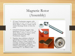
• 20 Large Neodymium magnets with dimensions of 3/2” x 3/4” x 1/2” (or about 38mm x 19mm x 13mm) will be stacked like Jenga blocks to form the rotor.
• 8 Small Neodymium magnets with dimensions of 3/4” x 1/4” x 1/2” (or about 19mm x 6mm x 13mm) will be stacked in between the large Neodymium magnets.
• Together these will form a flush fit around the 3/2”x1”x1” (or about 38mm x 25mm x 25mm) square nut assembly, resulting in a magnetic rotor assembly measuring 6” (or about 150mm) long with square poles faces measuring 3/2” (or 38mm) a side. |
|
Inserting the rotor
(Top)
| Wood Panels
(Disassembly)
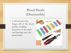
• I will unscrew the hinges off of the wood panels, enabling insertion of the shaft and bearings into the panel holes. |
| Bearings
(Phase 2 Parts)
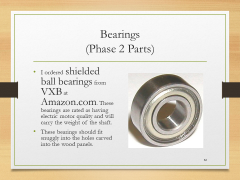
• I ordered shielded ball bearings from VXB at Amazon.com. These bearings are rated as having electric motor quality and will carry the weight of the shaft.
• These bearings should fit snuggly into the holes carved into the wood panels. |
| Inserting the Rotor
(Assembly)
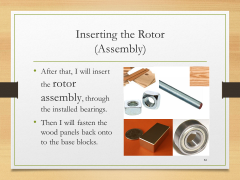
• After that, I will insert the rotor assembly, through the installed bearings.
• Then I will fasten the wood panels back onto to the base blocks. |
|
April 2016 Presentation
(Top)
| I
|

Introduction
Summary of measuring devices, back up and safety equipment, and camcorder (+accessories)
|
| 1
|
Phase 1
Holes, brass hinges, square nuts
|
| 2
|
Phase 2
Neodymium magnets and bearings
|
| 3
|
Phase 3
Spool, coils, and ceiling hooks
|
| 4
|
Phase 4
No hidden batteries, increase rigidity, hex nuts, terminal rings, toggle switch, fan blades, and extended test run
|
| 5
|
Phase 5
Heavy duty basket, S.H.O. Drive insertion, secure meters, and portable extended test run
|
| 6
|
Phase 6
Square tote, plastic spools, protective edge trim, and enclosed extended test run
|
| 7
|
Phase 7
Prepare elevated test platform, outdoor test setup, camcorder hookup to portable power, and outdoor extended test run
|
Site map
HQ ● Glossary ● April 2016 Presentation


