From S.H.O.
|
|
| Line 148: |
Line 148: |
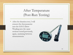
| | |Let's Build the S.H.O. Drive! - Slide 132 of 176.png||'''After Temperature'''<br>''(Post-Run Testing)''<br>• After the duration test, I will reinsert the thermometer into the S.H.O. Drive Winding into the same sections tested previously, again, sanitizing between measurements. | | |Let's Build the S.H.O. Drive! - Slide 132 of 176.png||'''After Temperature'''<br>''(Post-Run Testing)''<br>• After the duration test, I will reinsert the thermometer into the S.H.O. Drive Winding into the same sections tested previously, again, sanitizing between measurements. |
| | }} | | }} |
| | + | |
| | + | {{Presentation Explorer}} |
| | + | {{Site map}} |
Revision as of 14:14, 1 May 2016
In Phase 4…
• First on the list is to show that there are no hidden batteries inside the wood pieces.
• Second is to pre-drill and screw on additional wood pieces for added structural rigidity.
• Third is to adhere hex nuts on the shaft in order to lock the position of the rotor.
• Fourth on the list is to install ring connectors onto magnet wires where needed.
• Fifth is to screw the ring connectors on the toggle switch and secure the switch to the base with a mounting adhesive.
• Sixth is to install the fan blades on the shaft.
• Seventh is to run the S.H.O. Drive and measure the resistance, inductance, as well as the operational ampere current, rotational speed, temperature, and wind speed.
No hidden batteries
(Top)
| Transparency
(Protocols)
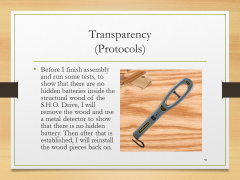
• Before I finish assembly and run some tests, to show that there are no hidden batteries inside the structural wood of the S.H.O. Drive, I will remove the wood and use a metal detector to show that there is no hidden battery. Then after that is established, I will reinstall the wood pieces back on. |
| S.H.O. Coils
(Disassembly)
• Before I can remove the wood panels, I need to first pull out the S.H.O. Coils from the installed ceiling hooks so that I can separate the panels from each other. |
| Wood Panels
(Disassembly)
• After the coils are removed, I then have to detach the wood panels from the base blocks by disconnecting the screws and hinges. For this I will use pieces from the iWork 53 piece Tool Set by Olympia Tools.
• The ceiling hooks can be unscrewed by hand. |
| Metal Detector
(Measuring Devices)
• In order to show that there are no hidden batteries inside the S.H.O. Drive wood pieces, I will use the GoerTek Portable Security Scanner that I purchased from GoerTek via Amazon.com |
|
Reinforcements
(Top)
| Metal Spring Clamps
(Recap)
• In Phase 1, in order to hold the wood pieces for pre-drilling, I used the Bessey XM7 3-Inch Metal Spring Clamps that I purchased from Woodcraft.
• I will use this again to conduct further pre-drilling for some additional structural reinforcements. |
| Compact Power Drill
(Recap)
• In Phase 1, I pre-drilled holes for the brass screws using the 18 Volt Cordless 3/8 in. Drill by Drill Master from Harbor Freight Tools. |
| Drill Bits
(Recap)
• In Phase 1, for drilling pilot holes for the brass screws, I used 3/32 in. Titanium Nitride High Speed Steel Drill Bits by Warrior from Harbor Freight Tools. |
| Spacers
(Phase 4 Parts)
• To ensure that the bearings stay inside the holes, I will screw in HighPoint Solid Brass Screws that I purchased from Woodcraft (after pre-drilling first) to attach very small spacers over the bearing holes. The spacers came with the Birdhouse kits. |
| Wide “Wood Shingle”
(Phase 4 Parts)
• The length of the two ash wood base blocks differ by 1/8”, so I will pre-drill through a “wide wood shingle” onto the end of one of the base blocks, and then I will screw in additional brass screws in order to secure the wide “wood shingle” into place. |
| X-Acto Knife
(Phase 4 Tools)
• In order to trim off the excess wood of the wide “wood shingle”, I will use an X-Acto Knife No. 1 with Cap that I purchased from an Artist & Craftsman Supply store. |
| Narrow “Wood Shingles”
(Parts)
• Additional brass screws will be used to secure two narrow “wood shingles” between each end of the two base blocks to lock them at a 45 degree tilt at both sides. |
|
Presentation back cover
(Top)
| #ShoDrives
@ShoDrives
Sho.wiki - Drive Replication and Collaboration Site
YouTube.com/c/ShoWiki - Watch and Subscribe Site
Facebook.com/ShoDrives - Like, Share, and Fan Site |
|
Finishing main unit assembly
(Top)
| S.H.O. Drive
(Reassembly)
• After the test with the metal detector and installing extra wood pieces, I will remove the “narrow shingles”, and then reinstall onto the wood panels the ceiling hooks, hinges, shaft, “narrow shingles”, and finally the two S.H.O. coils. |
| Hex Nuts
(Parts)
• I will secure the shaft with half-a-thread’s worth of special-purpose glue called Loctite Threadlocker Blue 242, which I purchased at Lowe’s.
• This will hold hex nuts on the shaft adjacent to the outer facings of the bearings. |
|
Connect toggle switch
(Top)
| Terminal Rings
(Phase 4 Parts)
• To connect the magnet wires onto the toggle switch, I will install 10-106 Terminal Rings from Gardner Bender, which I purchased from Amazon.com.
• I will crimp these onto the ends of the magnet wire and screw them onto the toggle switch terminals. |
| Sandpaper
(Tools)
• To maximize the connection between the terminal rings and the magnet wire, I will sand off the enamel layer at the ends of the wire using 3M 600 Grit sandpaper that I purchased from Lowe’s. |
| Crimper Tool
(Phase 4 Tools)
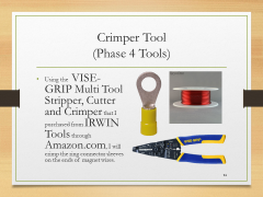
• Using the VISE-GRIP Multi Tool Stripper, Cutter and Crimper that I purchased from IRWIN Tools through Amazon.com, I will crimp the ring connector sleeves on the ends of magnet wires. |
| Toggle Switch
(Phase 4 Parts)
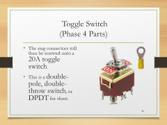
• The ring connectors will then be screwed onto a 20A toggle switch.
• This is a double-pole, double-throw switch, or DPDT for short. |
| Terminal Rings
(Assembly)
• To tighten the screws that will hold the terminal rings onto the toggle switch. I will again use pieces from the iWork 53 piece Tool Set by Olympia Tools. |
|
Toggle settings
(Top)
| ON/OFF Settings
(Operation)
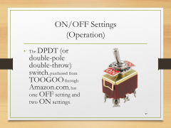
• The DPDT (or double-pole double-throw) switch, purchased from TOOGOO through Amazon.com, has one OFF setting and two ON settings. |
| OFF Setting
(Operation)
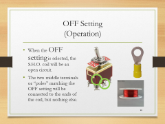
• When the OFF setting is selected, the S.H.O. coil will be an open circuit.
• The two middle terminals or “poles” matching the OFF setting will be connected to the ends of the coil, but nothing else. |
| On Setting #1
(Operation)
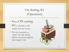
• When ON setting #1 is selected, it will simply close the circuit.
• The two terminals or “poles” for this setting will be connected together with magnet wire. |
| On Setting #2
(Operation)
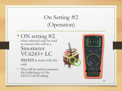
• ON setting #2, when selected, may be used to connect the coil to a Sinometer VC6243+ LC meter in series with the coils.
• This will be used to measure the Inductance of the S.H.O. Coil Winding. |
| LC meter
(Measuring Devices)
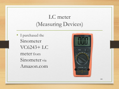
• I purchased the Sinometer VC6243+ LC meter from Sinometer via Amazon.com |
| LC meter
(Measuring Devices)
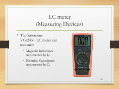
• The Sinometer VC6243+ LC meter can measure:
• Magnetic Inductance (represented by L)
• Electrical Capacitance (represented by C) |
| On Setting #2
(Operation)
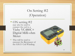
• ON setting #2 may also be used to connect the coil to a Vichy VC480C+ Digital Milli-ohm Meter.
• This will be used to measure the Resistance of the S.H.O. Coil Winding. |
| Milli-ohm Meter
(Measuring Devices)
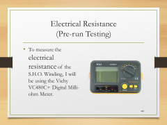
• I purchased the Vichy VC480C+ Digital Milli-ohm Meter from modders_chn via eBay.com |
| Milli-ohm Meter
(Measuring Devices)
• The Vichy VC480C+ Digital Milli-ohm Meter uses the 4-wire method of measuring very small resistances.
• The 4-wire method involves passing a current through a resistor and measuring the voltage across the terminals. |
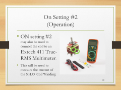
| On Setting #2
(Operation)
• ON setting #2 may also be used to connect the coil to an Extech 411 True-RMS Multimeter.
• This will be used to measure the current of the S.H.O. Coil Winding. |
| True-RMS Multimeter
(Measuring Devices)
• I purchased the Extech 411 True-RMS Multimeter from Fry’s Electronics. |
| True-RMS Multimeter
(Measuring Devices)
• The Extech 411 True-RMS Multimeter will be used calculate the root mean square or RMS of the current & voltage. |
| True-RMS Multimeter
(Measuring Devices)
• The heat loss in the winding can be calculated by taking the product of winding resistance and the mean square current. |
| True-RMS Multimeter
(Measuring Devices)
• This device does not measure the phase difference between current and voltage.
• Therefore, it cannot be used to measure power in a circuit with an inductor, capacitor, or other circuit components which may cause a phase difference between current and voltage.
• However, this meter can be used to calculate heat losses and measure induced voltage. |
|
Mounting and connections
(Top)
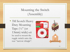
| Mounting the Switch
(Assembly)
• 3M Scotch Heavy Duty Mounting Tape (½” (or 13mm) wide) will be used to mount the toggle switch onto the rear “narrow shingle”. |
| Alligator Clip Leads
(Equipment)
• For better lead connections to On Setting #2, I purchased Heavy Duty 12 AWG - 3 Feet Long DC Power Supply Leads from PS-Mastech via Amazon.com. |
| Alligator Clip Leads
(Equipment)
• These leads have a wire size identical to the wire used in the S.H.O. Coil and therefore support a similar amount of current. These leads are gauge 12 on the American Wire Gauge scale.
• At one end, they have banana plugs which may be connected to the multimeters which I will be using.
• At the other end, these leads have alligator clips which can attach to the toggle switch at On Setting #2. |
|
Load assembly
(Top)
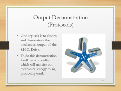
| Output Demonstration
(Protocols)
• One key task is to absorb and demonstrate the mechanical output of the S.H.O. Drive.
• To do this demonstration, I will use a propeller, which will transfer out mechanical energy to air, producing wind. |
| Fan Blades
(Phase 4 Parts)
• This Automotive cooling fan has 5 blades and has a diameter of 12” (or about 30 cm).
• I purchased this item from Flex-a-Lite through Amazon.com
• It’s part number 1312. |
| Washers and Hex Nuts
(Parts)
• I will secure the 12” (or 30 cm) diameter fan with its 5/8” (or 16 mm) bore hole, through the 5/8” (or 16 mm) diameter rod by compressing it between a pair of zinc-plated washers that I purchased at Lowe’s and a pair of zinc-plated hex nuts that I purchased at Tacoma Screw. |
| Adjustable Wrench
(Phase 4 Tools)
• To tighten the hex nuts against the washers and the propeller, I purchased a Kobalt 8-in (about 200 mm) Chrome Vanadium Steel Adjustable Wrench from Lowe’s. |
|
Testing setup and procedure
(Top)
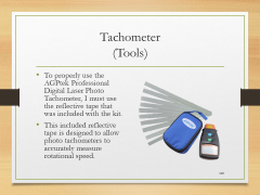
| Tachometer
(Measuring Devices)
• To measure rotation speed, I will use the AGPtek Professional Digital Laser Photo Tachometer that I purchased from AGPtek through Amazon.com |
| Tachometer
(Tools)
• To properly use the AGPtek Professional Digital Laser Photo Tachometer, I must use the reflective tape that was included with the kit.
• This included reflective tape is designed to allow photo tachometers to accurately measure rotational speed. |
| Compact Disc
(Compatibility)
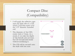
• I will apply the reflective tape onto the label side of a CD, which I will then insert over the 5/8” diameter threaded rod.
• The diameter of the CD’s center hole is 15mm. As a result, if you take the depth of the threads into account, the CD should hold steady without modifying it.
• The CD will be secured onto the shaft with hex nuts. |
| Plastic Furniture Tips
(Phase 4 Parts)
• To prevent the ends of the shaft from damaging things, I will cover them with 5/8” (or 16 mm) Black Plastic Furniture Tips from the Hillman Group that I purchased at Lowe’s. |
| Electrical Tape
(Parts)
• In order to form a tight grip between the shaft and the Plastic Furniture Tips, I will use the Scotch Professional Grade 35 Red Vinyl Electrical Tape, also from Lowe’s. |
| Electrical Resistance
(Pre-run Testing)
• To measure the electrical resistance of the S.H.O. Winding, I will be using the Vichy VC480C+ Digital Milli-ohm Meter. |
| Magnetic Inductance
(Pre-run Testing)
• To measure the magnetic inductance of the S.H.O. Winding as a function of rotor position, I will use the Sinometer VC6243+ LC meter. |
| Induced Voltage vs. Rotation
(Pre-run Testing)
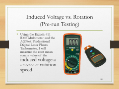
• Using the Extech 411 RMS Multimeter and the AGPtek Professional Digital Laser Photo Tachometer, I will measure the root mean square value of the induced voltage as a function of rotation speed. |
| Electric Current
(Run Testing)
• During the test run, I will use the Extech 411 RMS Multimeter to measure the root mean square value of the induced current. |
| Thermometer
(Tools)
• To measure the temperature of the coil, I will use the DTQ450X Quick-Read Thermometer from CDN that I purchased through Amazon.com
• This thermometer has a range of -40° F to +450° F (or -40° C to +230° C) |
| Thermometer Accuracy
(Pre-run Testing)
• I must test the thermometer to see if it takes accurate readings
• First, I will test the temperature of the air near the drive motor.
• Then, after sanitizing the thermometer with 70% isopropyl alcohol wipes, I will test the temperature under my tongue, which should be about 98.6 degrees Fahrenheit or 37 degrees Centigrade. |
| Before Temperature
(Pre-run Testing)
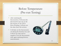
• After sanitizing the thermometer, I will insert the thermometer into one of the flat sections of the S.H.O. Drive Winding. I will also test the other three flat sections.
• I will take out the thermometer out during the duration test, and I will set up water and ice samples to test the thermometer with, again sanitizing between measurements. |
| Duration Run
(Run Testing)
• I will test a duration run of the drive motor. In this test, I will measure the S.H.O. Drive’s:
• Root mean square current
• Wind Speed
• Air Temperature
• Coil Temperature
• Rotational Speed |
| Anemometer
(Measuring Equipment)
• During the test run, I will measure the air speed in front and rear of the S.H.O. Drive fan, using the OriGlam Digital Anemometer & Thermometer from OriGlam that I purchased through Amazon.com
• This anemometer can measure winds between 196 and 4900 ft/min (2.2 and 56 mph) (3.6 and 90 kph). |
| After Temperature
(Post-Run Testing)
• After the duration test, I will reinsert the thermometer into the S.H.O. Drive Winding into the same sections tested previously, again, sanitizing between measurements. |
|
April 2016 Presentation
(Top)
| I
|

Introduction
Summary of measuring devices, back up and safety equipment, and camcorder (+accessories)
|
| 1
|

Phase 1
Holes, brass hinges, square nuts
|
| 2
|

Phase 2
Neodymium magnets and bearings
|
| 3
|

Phase 3
Spool, coils, and ceiling hooks
|
| 4
|

Phase 4
No hidden batteries, increase rigidity, hex nuts, terminal rings, toggle switch, fan blades, and extended test run
|
| 5
|

Phase 5
Heavy duty basket, S.H.O. Drive insertion, secure meters, and portable extended test run
|
| 6
|
Phase 6
Square tote, plastic spools, protective edge trim, and enclosed extended test run
|
| 7
|
Phase 7
Prepare elevated test platform, outdoor test setup, camcorder hookup to portable power, and outdoor extended test run
|
Site map
HQ ● Glossary ● April 2016 Presentation


