From S.H.O.
|
|
| Line 27: |
Line 27: |
| | <br>Since the coils were made before the magnets, I was unable to adapt the coils according to the new plan because they were made shorter (21" along the "S" path instead of 24") in anticipation of a smaller magnet assembly. Building the coils before the magnets was actually intentional because the thinking was that the coils were the most risky part and the goal was to build both the coils and the magnet in the same video. Instead, the magnet stack was built too large and the "S" coils have shortened arms with a "sticky spot", and so the rotor stops after only a few rotations after being pushed vigorously by hand. | | <br>Since the coils were made before the magnets, I was unable to adapt the coils according to the new plan because they were made shorter (21" along the "S" path instead of 24") in anticipation of a smaller magnet assembly. Building the coils before the magnets was actually intentional because the thinking was that the coils were the most risky part and the goal was to build both the coils and the magnet in the same video. Instead, the magnet stack was built too large and the "S" coils have shortened arms with a "sticky spot", and so the rotor stops after only a few rotations after being pushed vigorously by hand. |
| | <br>I also observed no acceleration effect at all when the magnet was moving through the horizontal angles (-/+ 45 degrees). The acceleration effect would have been due to the variation of intensity of the radially-directed part of the magnetic field at the outer radius of the "S". I have just remembered now that the reason for this variation was that the arms were to supposed to have reached all way to at least the "center plane" of the coils as one can observe in the S.H.O. Drive logo, which would cause a weakened intensity in the radial-directed part of the magnetic field at the "center plane" relative to its strength at the upper and lower parts of the "S". Also, it was known that the side-fluxes cutting through the central portion of the "S" would generate fields at the central plane opposing the rotation of the magnet, and in the actual build, it was these central fields that dominated due to the larger radius of the "S" in addition to the absence of flux cutting through the "S" hands when the magnet is in the horizontal position, flux cutting that ''would have'' helped the acceleration of the magnet if it were there at the central plane. But alas, the build was wrong! | | <br>I also observed no acceleration effect at all when the magnet was moving through the horizontal angles (-/+ 45 degrees). The acceleration effect would have been due to the variation of intensity of the radially-directed part of the magnetic field at the outer radius of the "S". I have just remembered now that the reason for this variation was that the arms were to supposed to have reached all way to at least the "center plane" of the coils as one can observe in the S.H.O. Drive logo, which would cause a weakened intensity in the radial-directed part of the magnetic field at the "center plane" relative to its strength at the upper and lower parts of the "S". Also, it was known that the side-fluxes cutting through the central portion of the "S" would generate fields at the central plane opposing the rotation of the magnet, and in the actual build, it was these central fields that dominated due to the larger radius of the "S" in addition to the absence of flux cutting through the "S" hands when the magnet is in the horizontal position, flux cutting that ''would have'' helped the acceleration of the magnet if it were there at the central plane. But alas, the build was wrong! |
| − | <br>The great advantage with the new design at (https://www.youtube.com/watch?v=huy53KdwAE4) is that it lacks any sort of sticky spots. In this newer design, the coil magnetic fields that dominate are the ones located at the outer radius. This is due to the tighter packing of the S-shape as compared to the older design. However, the magnets I had originally purchased were intended to make the magnet stack of 6" x 1.5" x 1.5" and they are unstable when set side-by-side horizontally. When I attempted to fit this "square peg" into round hole, the magnets decided form the rod-shaped magnet that I chose ''not'' to build. So the next step is to buy magnets capable of easily forming making the desired magnet arrangement as per (https://www.youtube.com/watch?v=huy53KdwAE4), and then fold the existing coils into the new design. The magnet pieces will be longer (up to 4" long), but thinner. This will aid in the build process, which should be finished before the end of this fall. Sincerely, ''[[User:S.H.O.|S.H.O.]] <sup>[[User_talk:S.H.O.|talk]]</sup>'' 17:40, 2 September 2016 (PDT) | + | <br>The great advantage with the new design at (https://www.youtube.com/watch?v=huy53KdwAE4) is that it lacks any sort of sticky spots. In this newer design, the coil magnetic fields that dominate are the ones located at the outer radius. This is due to the tighter packing of the S-shape as compared to the older design. However, the magnets I had originally purchased were intended to make the magnet stack of 6" x 1.5" x 1.5" and they are unstable when set side-by-side horizontally. When I attempted to fit this "square peg a into round hole", the magnets decided form the rod-shaped magnet that I chose ''not'' to build. So the next step is to buy magnets capable of easily forming making the desired magnet arrangement as per (https://www.youtube.com/watch?v=huy53KdwAE4), and then fold the existing coils into the new design. The magnet pieces will be longer (up to 4" long), but thinner. This will aid in the build process, which should be finished before the end of this fall. Sincerely, ''[[User:S.H.O.|S.H.O.]] <sup>[[User_talk:S.H.O.|talk]]</sup>'' 17:40, 2 September 2016 (PDT) |
| | | | |
| | ==Presentation Outline (for S.H.O. Drive Alpha)== | | ==Presentation Outline (for S.H.O. Drive Alpha)== |
Revision as of 18:09, 2 September 2016
S.H.O. Drive Mark I will be the world's first S.H.O. drive (unless proven otherwise of course) ;).
S.H.O. Drive Mark I will be the world's first S.H.O. drive. Come back in the next couple months for major updates! S.H.O. talk 21:35, 5 May 2016 (PDT)
S.H.O. Drive Mark Alpha refers to the original plan for world's first S.H.O. Drive (April 18, 2016). The actual build will incorporate clear acrylic tubes to elevate the wooden panels inside the crate for maximum transparency and minimization of the ways to hide batteries. A build and demonstration was planned for the 4th of July, but I decided that more planning was need in terms of the logistics of the demonstration as well as the final shape of the S.H.O. Coils. The build time to make the S.H.O. Drive is, and I estimate, to be around 5 hours. Since the video showing the build must be done in one take, I have to make sure that I have my ideas lined up, so this way they come out smoothly in the presentation.
Also, cost information is not listed for S.H.O. Drive Alpha because it is preliminary work, but when the world's first S.H.O. drive is built, the cost information for that build will be made available. Sincerely, S.H.O. talk 20:06, 4 July 2016 (PDT)
Wood of any kind has been completely eliminated from the planned S.H.O. Drive build. The acrylic rods have been cut (August 14, 2016), and the coils and magnets have been assembled (August 26, 2016). However, the magnets were not built according to the new plan due to assembly mishaps. So the bending of the rectangular copper windings need to be rethought, but definitely into a different S-shape. The "S-arms" will have about the same length but over fewer degrees of arc due to a larger radius. The "S-arms" will likely have "hands" bent away, radially, from the shaft to reduce drag. Also newly accounted for is the increase of the phase angle between the voltage and current as rpm increases, and so the "S-arms" will be planned to have around 90 to 135 degrees of arc. S.H.O. talk 11:48, 28 August 2016 (PDT)
Initial Test Results

Original S.H.O. Drive Plans.
Compare to the most recent plan:
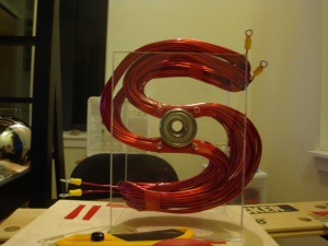
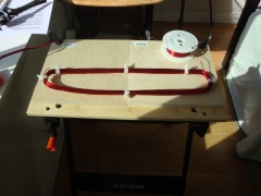
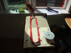
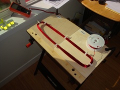
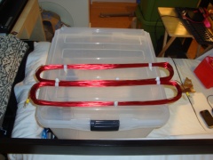
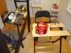
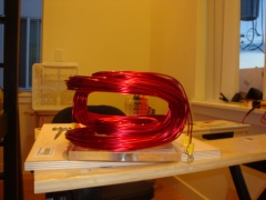
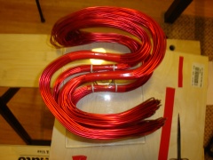
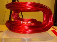
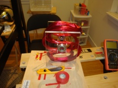
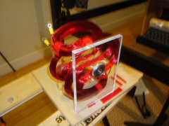
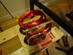
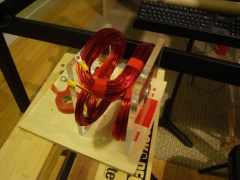
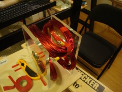
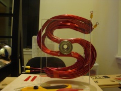
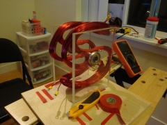
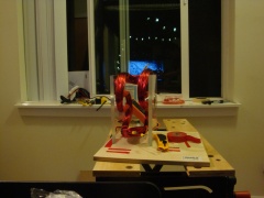
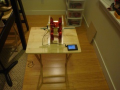
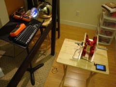
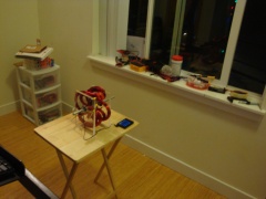
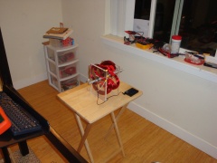
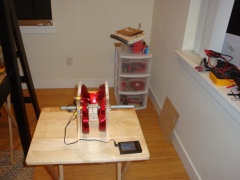
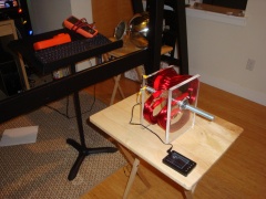
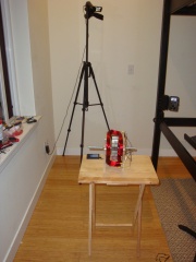
First actual build of S.H.O. Coils
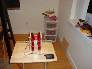
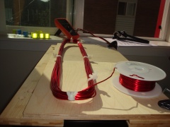
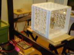
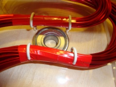
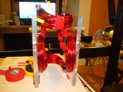
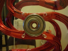
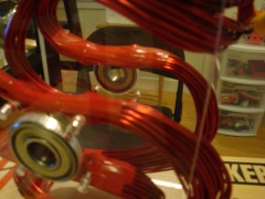
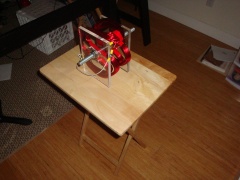
First actual build of S.H.O. Coils (magnets inside)
The magnets were not assembled according to the most recent planned design at (https://www.youtube.com/watch?v=huy53KdwAE4) due to difficulties encountered during the assembly procedure. The magnets that were purchased "insisted" that they form a rod-shaped magnet. As a result, it resembled an earlier design (based on a magnet stack of dimensions of 6" x 1.5" x 1.5"). The most recent planned design (https://www.youtube.com/watch?v=huy53KdwAE4) is very different than prior plans of the S.H.O. Drive because it was uncertain that earlier designs would work at all.
The key issue with earlier designs was that the original thinking was that the influence of the side fluxes were minimal and so that the magnet would operate by interacting with the magnetic field that was inverted in the center. As it turns out, in the original geometry, they account for about half of the magnetic flux linkage in the system. Subsequently upon realizing this mistake, it was originally thought that the variation of the intensity of the magnetic fields at the outer radius of the "S" coils would cause attraction that would cause rotation in the desired direction when the magnet was angularly displaced through horizontal angles (-/+ 45 degrees). However, it was also known that if the arms were too short that there would be a "sticky spot" where the magnet would slow down, although whether it was to a stop was at the time yet to be determined.
Since the coils were made before the magnets, I was unable to adapt the coils according to the new plan because they were made shorter (21" along the "S" path instead of 24") in anticipation of a smaller magnet assembly. Building the coils before the magnets was actually intentional because the thinking was that the coils were the most risky part and the goal was to build both the coils and the magnet in the same video. Instead, the magnet stack was built too large and the "S" coils have shortened arms with a "sticky spot", and so the rotor stops after only a few rotations after being pushed vigorously by hand.
I also observed no acceleration effect at all when the magnet was moving through the horizontal angles (-/+ 45 degrees). The acceleration effect would have been due to the variation of intensity of the radially-directed part of the magnetic field at the outer radius of the "S". I have just remembered now that the reason for this variation was that the arms were to supposed to have reached all way to at least the "center plane" of the coils as one can observe in the S.H.O. Drive logo, which would cause a weakened intensity in the radial-directed part of the magnetic field at the "center plane" relative to its strength at the upper and lower parts of the "S". Also, it was known that the side-fluxes cutting through the central portion of the "S" would generate fields at the central plane opposing the rotation of the magnet, and in the actual build, it was these central fields that dominated due to the larger radius of the "S" in addition to the absence of flux cutting through the "S" hands when the magnet is in the horizontal position, flux cutting that would have helped the acceleration of the magnet if it were there at the central plane. But alas, the build was wrong!
The great advantage with the new design at (https://www.youtube.com/watch?v=huy53KdwAE4) is that it lacks any sort of sticky spots. In this newer design, the coil magnetic fields that dominate are the ones located at the outer radius. This is due to the tighter packing of the S-shape as compared to the older design. However, the magnets I had originally purchased were intended to make the magnet stack of 6" x 1.5" x 1.5" and they are unstable when set side-by-side horizontally. When I attempted to fit this "square peg a into round hole", the magnets decided form the rod-shaped magnet that I chose not to build. So the next step is to buy magnets capable of easily forming making the desired magnet arrangement as per (https://www.youtube.com/watch?v=huy53KdwAE4), and then fold the existing coils into the new design. The magnet pieces will be longer (up to 4" long), but thinner. This will aid in the build process, which should be finished before the end of this fall. Sincerely, S.H.O. talk 17:40, 2 September 2016 (PDT)
Presentation Outline (for S.H.O. Drive Alpha)
Presentation
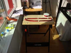
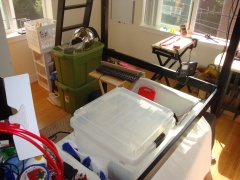
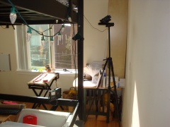
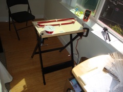
Build Gallery
August 14, 2016
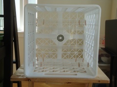
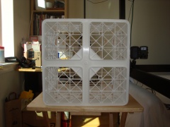
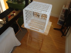
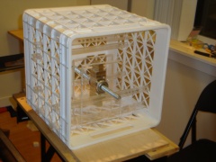
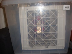
| S.H.O. Drive Crate
Rear View |
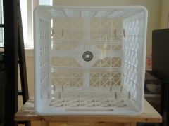
| S.H.O. Drive Crate
Rear View (Leveled) |
| S.H.O. Drive Crate
Rear View (with flash) |
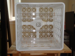
| S.H.O. Drive Crate
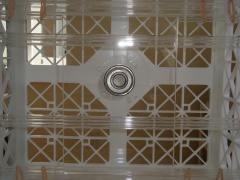
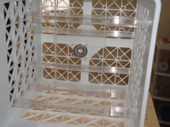
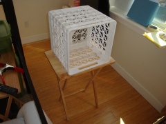
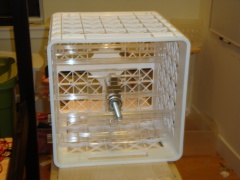
Interior View |
| S.H.O. Drive Crate
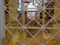
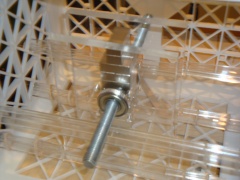
Interior View (Center) |
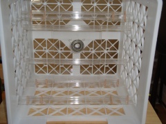
| S.H.O. Drive Crate
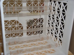
Interior View from Rear (revealing left-side wall) |
| S.H.O. Drive Crate
Interior View from Rear (revealing right-side wall) |
| S.H.O. Drive Crate
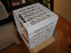
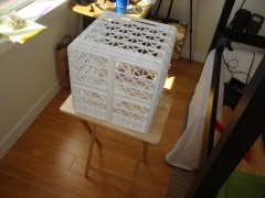
Diagonal View (Top Left Rear) |
| S.H.O. Drive Crate
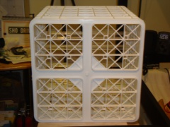
Front View |
| S.H.O. Drive Crate
Diagonal View (Top Front) |
| S.H.O. Drive Crate
Diagonal View (Top Left Front) |
| S.H.O. Drive Crate
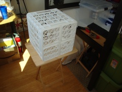
Diagonal View (Top Right Rear) |
| S.H.O. Drive Crate
Diagonal View (Top Rear) |
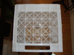
| S.H.O. Drive Crate
Top View |
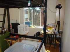
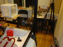
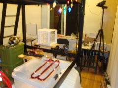
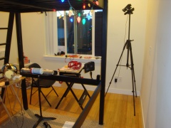
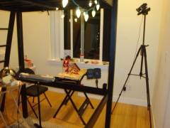
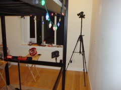
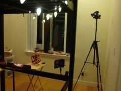
| S.H.O. Drive Build Room
on August 14, 2016 (with North Wall) |
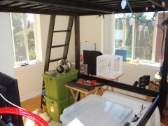
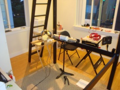
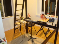
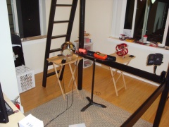
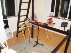
| S.H.O. Drive Build Room
on August 14, 2016 (with South Wall) |
|
August 26, 2016
| 2nd S.H.O. Drive Build Day (2016.08.26)
Picture 1 of 29 |
| 2nd S.H.O. Drive Build Day (2016.08.26)
Picture 2 of 29 |
| 2nd S.H.O. Drive Build Day (2016.08.26)
Picture 3 of 29 |
| 2nd S.H.O. Drive Build Day (2016.08.26)
Picture 4 of 29 |
| 2nd S.H.O. Drive Build Day (2016.08.26)
Picture 5 of 29 |
| 2nd S.H.O. Drive Build Day (2016.08.26)
Picture 6 of 29 |
| 2nd S.H.O. Drive Build Day (2016.08.26)
Picture 7 of 29 |
| 2nd S.H.O. Drive Build Day (2016.08.26)
Picture 8 of 29 |
| 2nd S.H.O. Drive Build Day (2016.08.26)
Picture 9 of 29 |
| 2nd S.H.O. Drive Build Day (2016.08.26)
Picture 10 of 29 |
| 2nd S.H.O. Drive Build Day (2016.08.26)
Picture 11 of 29 |
| 2nd S.H.O. Drive Build Day (2016.08.26)
Picture 12 of 29 |
| 2nd S.H.O. Drive Build Day (2016.08.26)
Picture 13 of 29 |
| 2nd S.H.O. Drive Build Day (2016.08.26)
Picture 14 of 29 |
| 2nd S.H.O. Drive Build Day (2016.08.26)
Picture 15 of 29 |
| 2nd S.H.O. Drive Build Day (2016.08.26)
Picture 16 of 29 |
| 2nd S.H.O. Drive Build Day (2016.08.26)
Picture 17 of 29 |
| 2nd S.H.O. Drive Build Day (2016.08.26)
Picture 18 of 29 |
| 2nd S.H.O. Drive Build Day (2016.08.26)
Picture 19 of 29 |
| 2nd S.H.O. Drive Build Day (2016.08.26)
Picture 20 of 29 |
| 2nd S.H.O. Drive Build Day (2016.08.26)
Picture 21 of 29 |
| 2nd S.H.O. Drive Build Day (2016.08.26)
Picture 22 of 29 |
| 2nd S.H.O. Drive Build Day (2016.08.26)
Picture 23 of 29 |
| 2nd S.H.O. Drive Build Day (2016.08.26)
Picture 24 of 29 |
| 2nd S.H.O. Drive Build Day (2016.08.26)
Picture 25 of 29 |
| 2nd S.H.O. Drive Build Day (2016.08.26)
Picture 26 of 29 |
| 2nd S.H.O. Drive Build Day (2016.08.26)
Picture 27 of 29 |
| 2nd S.H.O. Drive Build Day (2016.08.26)
Picture 28 of 29 |
| 2nd S.H.O. Drive Build Day (2016.08.26)
Picture 29 of 29 |
|
August 30-31, 2016
| 3rd S.H.O. Drive Build Day (2016.08.30)
Picture 1 of 43 |
| 3rd S.H.O. Drive Build Day (2016.08.30)
Picture 2 of 43 |
| 3rd S.H.O. Drive Build Day (2016.08.30)
Picture 3 of 43 |
| 3rd S.H.O. Drive Build Day (2016.08.30)
Picture 4 of 43 |
| 3rd S.H.O. Drive Build Day (2016.08.30)
Picture 5 of 43 |
| 3rd S.H.O. Drive Build Day (2016.08.30)
Picture 6 of 43 |
| 3rd S.H.O. Drive Build Day (2016.08.30)
Picture 7 of 43 |
| 3rd S.H.O. Drive Build Day (2016.08.30)
Picture 8 of 43 |
| 3rd S.H.O. Drive Build Day (2016.08.30)
Picture 9 of 43 |
| 3rd S.H.O. Drive Build Day (2016.08.30)
Picture 10 of 43 |
| 3rd S.H.O. Drive Build Day (2016.08.30)
Picture 11 of 43 |
| 3rd S.H.O. Drive Build Day (2016.08.30)
Picture 12 of 43 |
| 3rd S.H.O. Drive Build Day (2016.08.30)
Picture 13 of 43 |
| 3rd S.H.O. Drive Build Day (2016.08.30)
Picture 14 of 43 |
| 3rd S.H.O. Drive Build Day (2016.08.30)
Picture 15 of 43 |
| 3rd S.H.O. Drive Build Day (2016.08.30)
Picture 16 of 43 |
| 3rd S.H.O. Drive Build Day (2016.08.30)
Picture 17 of 43 |
| 3rd S.H.O. Drive Build Day (2016.08.30)
Picture 18 of 43 |
| 3rd S.H.O. Drive Build Day (2016.08.30)
Picture 19 of 43 |
| 3rd S.H.O. Drive Build Day (2016.08.30)
Picture 20 of 43 |
| 3rd S.H.O. Drive Build Day (2016.08.30)
Picture 21 of 43 |
| 3rd S.H.O. Drive Build Day (2016.08.30)
Picture 22 of 43 |
| 3rd S.H.O. Drive Build Day (2016.08.30)
Picture 23 of 43 |
| 3rd S.H.O. Drive Build Day (2016.08.30)
Picture 24 of 43 |
| 3rd S.H.O. Drive Build Day (2016.08.30)
Picture 25 of 43 |
| 3rd S.H.O. Drive Build Day (2016.08.30)
Picture 26 of 43 |
| 3rd S.H.O. Drive Build Day (2016.08.30)
Picture 27 of 43 |
| 3rd S.H.O. Drive Build Day (2016.08.31)
Picture 28 of 43 |
| 3rd S.H.O. Drive Build Day (2016.08.31)
Picture 29 of 43 |
| 3rd S.H.O. Drive Build Day (2016.08.31)
Picture 30 of 43 |
| 3rd S.H.O. Drive Build Day (2016.08.31)
Picture 31 of 43 |
| 3rd S.H.O. Drive Build Day (2016.08.31)
Picture 32 of 43 |
| 3rd S.H.O. Drive Build Day (2016.08.31)
Picture 33 of 43 |
| 3rd S.H.O. Drive Build Day (2016.08.31)
Picture 34 of 43 |
| 3rd S.H.O. Drive Build Day (2016.08.31)
Picture 35 of 43 |
| 3rd S.H.O. Drive Build Day (2016.08.31)
Picture 36 of 43 |
| 3rd S.H.O. Drive Build Day (2016.08.31)
Picture 37 of 43 |
| 3rd S.H.O. Drive Build Day (2016.08.31)
Picture 38 of 43 |
| 3rd S.H.O. Drive Build Day (2016.08.31)
Picture 39 of 43 |
| 3rd S.H.O. Drive Build Day (2016.08.31)
Picture 40 of 43 |
| 3rd S.H.O. Drive Build Day (2016.08.31)
Picture 41 of 43 |
| 3rd S.H.O. Drive Build Day (2016.08.31)
Picture 42 of 43 |
| 3rd S.H.O. Drive Build Day (2016.08.31)
Picture 43 of 43 |
|
August 31, 2016
| Moving Day (2016.08.31)
Picture 1 of 7 |
| Moving Day (2016.08.31)
Picture 2 of 7 |
| Moving Day (2016.08.31)
Picture 3 of 7 |
| Moving Day (2016.08.31)
Picture 4 of 7 |
| Moving Day (2016.08.31)
Picture 5 of 7 |
| Moving Day (2016.08.31)
Picture 6 of 7 |
| Moving Day (2016.08.31)
Picture 7 of 7 |
|
Dimensions
Distance along shaft length (Depth)
 For design plan as of August 14, 2016

 inches
 1 7/8 back end assembly behind panel
 5/8   square acrylic support rod
 1/4   square acrylic support rod
 1/2   acrylic panel
 7/8   vinyl cup hooks
 3/8   air gap
 1 1/2 neo magnets
 3/8   air gap
 7/8   vinyl cup hooks
 1/2   acrylic panel
 1/4   square acrylic support rod
 5/8   square acrylic support rod
 3 3/8 front end assembly in front of panel

 12    total length of shaft
For design plan as of August 28, 2016
April 2016 Presentation
(Top)
| I
|

Introduction
Summary of measuring devices, back up and safety equipment, and camcorder (+accessories)
|
| 1
|
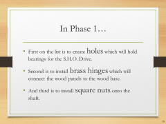
Phase 1
Holes, brass hinges, square nuts
|
| 2
|
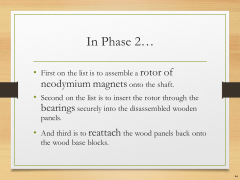
Phase 2
Neodymium magnets and bearings
|
| 3
|
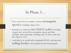
Phase 3
Spool, coils, and ceiling hooks
|
| 4
|
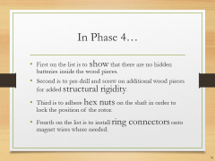
Phase 4
No hidden batteries, increase rigidity, hex nuts, terminal rings, toggle switch, fan blades, and extended test run
|
| 5
|
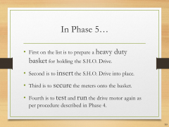
Phase 5
Heavy duty basket, S.H.O. Drive insertion, secure meters, and portable extended test run
|
| 6
|
Phase 6
Square tote, plastic spools, protective edge trim, and enclosed extended test run
|
| 7
|
Phase 7
Prepare elevated test platform, outdoor test setup, camcorder hookup to portable power, and outdoor extended test run
|
Site map
HQ ● Glossary ● April 2016 Presentation


