|
|
| (28 intermediate revisions by the same user not shown) |
| Line 1: |
Line 1: |
| − | | + | {{#seo: |
| − | <center>
| + | |title=April 2016 Presentation @ Sho Drives Wiki |
| − | ==Introduction==
| + | |titlemode=replace |
| − | {{Gallery | + | |keywords=electricity,magnetism,motor,generator |
| − | |width=360 | + | |description=Presenting the S.H.O. Drive! PNG and PowerPoint available. |
| − | |align=center | + | |
| − | |lines=10 | + | |
| − | |footer=
| + | |
| − | |Let's Build the S.H.O. Drive! - Slide 001 of 176.png||'''Let’s Build The<br>S.H.O. Drive'''<br>• This <sup><big>'''''is'''''</big></sup> a guide to a series of videos where I will construct the world’s first S.H.O. Drive. This will be the first drive motor in the world to have a coil that looks like an S, or an H, or an O, depending on which side you look from. S.H.O. also stands for “Side Hung Over”. What good is this for? The best way to know is to build one yourself and show it! So let’s begin!
| + | |
| − | |Let's Build the S.H.O. Drive! - Slide 002 of 176.png||'''Measuring Devices'''<br>''(Equipment)''<br>• This project involves many measuring devices, including analog and digital thermometers, a laser tachometer, a Milli-Ohm meter, an RMS meter, a LC meter, an Anemometer, a magnetic pole detector, and a metal detector. | + | |
| − | |Let's Build the S.H.O. Drive! - Slide 003 of 176.png||'''Rechargeable Batteries'''<br>''(Energy)''<br>• Some of these devices come with non-rechargeable batteries. When these run out, they will need to be replaced.<br>• Where possible, rechargeable batteries will be used after the old batteries are used up.
| + | |
| − | |Let's Build the S.H.O. Drive! - Slide 004 of 176.png||'''Non-Rechargeable Batteries'''<br>''(Energy)''<br>• Some of the measuring devices require watch-type batteries, so for these devices, non-rechargeable batteries will be used.
| + | |
| − | |Let's Build the S.H.O. Drive! - Slide 005 of 176.png||'''Fuses'''<br>''(Equipment)''<br>• Most multimeters have built-in fuses. These fuses are designed to burn out when overheated due to excessive current.<br>• So as a matter of preparation, I have purchased compatible replacement fuses.
| + | |
| − | |Let's Build the S.H.O. Drive! - Slide 006 of 176.png||'''20 Amp Fuses'''<br>''(Equipment)''<br>• For 20 Amp protection, I purchased a 2-pack of Bussmann BP/ABC-20 20 Amp Fast Blow Fuses from Bussmann via Amazon.com
| + | |
| − | |Let's Build the S.H.O. Drive! - Slide 007 of 176.png||'''200 Milliamp Fuses'''<br>''(Equipment)''<br>• For 200 mA protection, I purchased a 5-pack of Bussmann GMA 200mA Fast-Blow Fuses from Divine Lighting via Amazon.com
| + | |
| − | |Let's Build the S.H.O. Drive! - Slide 008 of 176.png||'''Fire Extinguisher'''<br>''(Equipment)''<br>• In a worst-case scenario, the project may catch on fire due to overheating.<br>• To reduce the losses associated with such a fire, I must have a fire extinguisher at hand.
| + | |
| − | |Let's Build the S.H.O. Drive! - Slide 009 of 176.png||'''Fire Extinguisher'''<br>''(Equipment)''<br>• So for basic safety requirements, I purchased the Amerex B500, 5lb ABC Dry Chemical Class A B C Fire Extinguisher from Amerex via Amazon.com
| + | |
| − | |Let's Build the S.H.O. Drive! - Slide 010 of 176.png||'''Safety Gear'''<br>''(Equipment)''<br>• For safety, I purchased SAS safety goggles, an SAS First Aid Kit, and FastCap Skins Gloves, which I found in extra large.<br>• I purchased these and more at a wood-working specialty store called Woodcraft.
| + | |
| − | |Let's Build the S.H.O. Drive! - Slide 011 of 176.png||'''Safety Gear'''<br>''(Equipment)''<br>• Since my wood-working operations will be limited to sanding and drilling small holes and grooves, I will use a Western Safety Dust and Particle Mask so as to not inhale any saw dust.<br>• I purchased this from a Harbor Freight Tools store.
| + | |
| − | |Let's Build the S.H.O. Drive! - Slide 012 of 176.png||'''Visual Evidence'''<br>''(Protocols)''<br>• After the S.H.O. Drive is built, tests will follow.<br>• The plan is to run extended duration tests, some which will run for hours, and others for days.<br>• An appropriate video recording device is required to provide a visual record for these tests as they happen.
| + | |
| − | |Let's Build the S.H.O. Drive! - Slide 013 of 176.png||'''Camcorder'''<br>''(Recording)''<br>• To provide evidence for these tests, I have purchased a Canon VIXIA HF R60 Camcorder from Canon via Amazon.com
| + | |
| − | |Let's Build the S.H.O. Drive! - Slide 014 of 176.png||'''Camcorder'''<br>''(Recording)''<br>• This camcorder can record up to 12 hours at normal recording speed and also has a time-lapse function to record video over several days, or more.<br>• It can capture video at 60 progressive frames per second.
| + | |
| − | |Let's Build the S.H.O. Drive! - Slide 015 of 176.png||'''Memory Card'''<br>''(Recording)''<br>• In order to record and save very long videos, I purchased the Transcend 128GB SDXC Class 10 UHS-1 Flash Memory Card from Transcend via Amazon.com
| + | |
| − | |Let's Build the S.H.O. Drive! - Slide 016 of 176.png||'''Adjustable Clamp Mount'''<br>''(Recording)''<br>• To record video at the desired angle, I have purchased the 13.4" Smatree Adjustable Jaws Flex Clamp Mount from Smatree via Amazon.com
| + | |
| − | |Let's Build the S.H.O. Drive! - Slide 017 of 176.png||'''Wide Angle Lens Kit'''<br>''(Recording)''<br>• In order to capture a wider angle of view in the video, I purchased a Wide Angle Lens Kit from ButterflyPhoto via Amazon.com<br>• The included .43x Wide Angle Lens provides a better approximation of human vision.
| + | |
| | }} | | }} |
| − | <div style="clear:both"></div>
| + | {{DISPLAYTITLE:April 2016 Presentation}} |
| − | ==Phase 1==
| + | [[File:Let's Build the S.H.O. Drive! - Slide 001 of 176.png|thumb|link=File:Let's Build the S.H.O. Drive!.pptx|<div style="float: right">[http://www.sho.wiki/images/Let%27s_Build_the_S.H.O._Drive%21.pptx ''Let's Build the S.H.O. Drive!.pptx''] (68 MB)</div>]] |
| − | {{Gallery | + | '''Let’s Build The S.H.O. Drive!'''<br>• This <sup><big>'''''is'''''</big></sup> a guide to a series of videos where I will construct the world’s first S.H.O. Drive.<br>• This will be the first drive motor in the world to have a coil that looks like an S, or an H, or an O, depending on which side you look from.<br>• S.H.O. also stands for “Side Hung Over”.<br>• What good is this for? The best way to know is to build one yourself and show it! So let’s begin! |
| − | |width=360
| + | |
| − | |align=center
| + | |
| − | |lines=10
| + | |
| − | |footer=
| + | |
| − | |Let's Build the S.H.O. Drive! - Slide 018 of 176.png||'''In Phase 1…'''<br>• First on the list is to create holes which will hold bearings for the S.H.O. Drive.<br>• Second is to install brass hinges which will connect the wood panels to the wood base.<br>• And third is to install square nuts onto the shaft.
| + | |
| − | |Let's Build the S.H.O. Drive! - Slide 019 of 176.png||'''2 Barn Birdhouse Kits'''<br>''(Phase 1 Parts)''<br>• The wood panels I will be using will come from 2 SawDust Bros. Birdhouse Kits which I obtained from Woodcraft.<br>• Why birdhouse kits? Well each birdhouse kit is packed with many pieces of wood of various sizes, which I may use in the future.
| + | |
| − | |Let's Build the S.H.O. Drive! - Slide 020 of 176.png||'''Saving Time'''<br>''(Protocols)''<br>• But the main reason why I purchased two Birdhouse kits was for the two front panels, which have holes that are nearly the right size for the project.<br>• I will use the front panels from each kit as support structures to carry the weight of the bearings, rotor, and conductive copper coils.
| + | |
| − | |Let's Build the S.H.O. Drive! - Slide 021 of 176.png||'''Hole Size'''<br>''(Compatibility)''<br>• Each front panel already has a conveniently placed 1½”‘‘‘<br>''(or about 38 mm) hole which I will expand by 1/8”‘‘‘<br>''(or about 3 mm) to hold the bearings.<br>• The bearings will be introduced in Phase 2.<br>• Each front panel has a base side measurement of 6”‘‘‘<br>''(or about 150 mm). Also, they have a thickness of ½”‘‘‘<br>''(or about 13 mm).
| + | |
| − | |Let's Build the S.H.O. Drive! - Slide 022 of 176.png||'''Circle Template'''<br>''(Phase 1 Tools)''<br>• To mark the dimensions for the 1 5/8 ” (or about 41 mm) bearing holes, I bought a 42 circle template sheet by Timely from a specialty store called Artist & Craftsman Supply.
| + | |
| − | |Let's Build the S.H.O. Drive! - Slide 023 of 176.png||'''Power Drill'''<br>''(Phase 1 Tools)''<br>• To expand the holes for the bearings, I purchased an inexpensive rotary tool from Ferm via Amazon.com.
| + | |
| − | |Let's Build the S.H.O. Drive! - Slide 024 of 176.png||'''Portable Work Bench'''<br>''(Equipment)''<br>• I purchased from Black & Decker the WM125 Workmate through Amazon.com, which is foldable and has an adjustable width.<br>• The clamping wood pieces have a groove which, fortuitously, can hold the depth guide of the power drill. So this work bench will effectively function as an inexpensive “router table”.
| + | |
| − | |Let's Build the S.H.O. Drive! - Slide 025 of 176.png||'''Dremel Accessory Set'''<br>''(Phase 1 Tools)''<br>• In order to finish the holes nicely to size, I will attach items from the Dremel 687-01 General Purpose Accessory Set I purchased at Fry’s Electronics.
| + | |
| − | |Let's Build the S.H.O. Drive! - Slide 026 of 176.png||'''Sanding Bands & Drum'''<br>''(Phase 1 Tools)''<br>• The Dremel tools from the kit that I will use are the 432 Sanding Bands and the 407 Sanding Drum.<br>• The sanding area will be ½” (or about 13 mm) thick, which will be perfect for sanding into the ½” (or about 13 mm) thick wood panels which will hold the bearings.
| + | |
| − | |Let's Build the S.H.O. Drive! - Slide 027 of 176.png||'''Plywood Surface'''<br>''(Equipment)''<br>• To make better use of the workbench for the rest of the project, I will cover the top with two pieces of Baltic Birch plywood from Woodcraft:<br>• The side lengths are 12” (or about 30 cm)<br>• The thickness of each is 1/2” (or about 13 mm)
| + | |
| − | |Let's Build the S.H.O. Drive! - Slide 028 of 176.png||'''C-Clamps'''<br>''(Equipment)''<br>• To hold the plywood to the workbench, I will use 3 in. Industrial C-Clamps that I obtained from a Harbor Freight Tools store.
| + | |
| − | |Let's Build the S.H.O. Drive! - Slide 029 of 176.png||'''Ash Wood Blocks'''<br>''(Phase 1 Parts)''<br>• I also have two separate Ash wood blocks, also from Woodcraft that are about 2 inches by 2 inches thick. That’s about 50 millimeters on each side. Their length is about 8 inches long, or about 200 millimeters. These blocks will serve as the “feet” of the S.H.O. Drive.<br>• If you’re wondering what Ash wood is used for, it’s a wood often used in baseball bats.
| + | |
| − | |Let's Build the S.H.O. Drive! - Slide 030 of 176.png||'''Brass Hinges'''<br>''(Phase 1 Parts)''<br>• So how should I attach these panels to the base blocks? Well I could simply glue and nail these panels to the base like a normal person. But here I will do something different. <br>• From Woodcraft, I purchased these brass hinges, which I will use to attach the panels onto the ash wood blocks.
| + | |
| − | |Let's Build the S.H.O. Drive! - Slide 031 of 176.png||'''Transparency'''<br>''(Protocols)''<br>• I am a bit extra-concerned about the craftsmanship of this effort, and it would obviously be simpler to glue and nail the pieces together. But I place more value in reducing the possible ways that are available to “trick” this device.
| + | |
| − | |Let's Build the S.H.O. Drive! - Slide 032 of 176.png||'''Transparency'''<br>''(Protocols)''<br>• Furthermore, the device, when completed will be left uncovered and exposed to the surrounding elements and operated in multiple environments to reduce the number ways to trick this device.
| + | |
| − | |Let's Build the S.H.O. Drive! - Slide 033 of 176.png||'''Transparency'''<br>''(Protocols)''<br>• I do want this device to be well-built enough to operate even when transporting it, to better distinguish it from rather immobile devices which, who knows, could be powered by an object hiding behind a wall or some other structure in the room.
| + | |
| − | |Let's Build the S.H.O. Drive! - Slide 034 of 176.png||'''Metal Spring Clamps'''<br>''(Equipment)''<br>• Before drilling the pilot holes for the brass screws, I will clamp the Ash wood base blocks with Bessey XM7 3-Inch Metal Spring Clamps that I purchased from Woodcraft.
| + | |
| − | |Let's Build the S.H.O. Drive! - Slide 035 of 176.png||'''Power Drill'''<br>''(Recap)''<br>• Earlier in this construction Phase, I will have used a rotary tool from Ferm and the Dremel 407 Sanding Drum to make neat circular holes for the bearings.
| + | |
| − | |Let's Build the S.H.O. Drive! - Slide 036 of 176.png||'''Compact Power Drill'''<br>''(Tools)''<br>• However, to drill pilot holes for the brass screws, I will use an 18 Volt Cordless 3/8 in. Drill by Drill Master from Harbor Freight Tools. 3/8 in. is about 9.5 millimeters.
| + | |
| − | |Let's Build the S.H.O. Drive! - Slide 037 of 176.png||'''Drill Bits'''<br>''(Tools)''<br>• I also purchased a set of 3/32 in. Titanium Nitride High Speed Steel Drill Bits by Warrior from Harbor Freight Tools.<br>• These will allow to me drill pilot holes into the Ash wood base blocks for the screws.
| + | |
| − | |Let's Build the S.H.O. Drive! - Slide 038 of 176.png||'''Brass Screws'''<br>''(Parts)''<br>• After drilling the pilot holes, I will screw the hinges tight with HighPoint Solid Brass Screws that I purchased from Woodcraft.<br>• These are size #6 so they have a diameter of 5/16 in. (or about 8 mm) measured at the shank. The shank is the straight section next to the head of each screw.
| + | |
| − | |Let's Build the S.H.O. Drive! - Slide 039 of 176.png||'''Screw Driver Set'''<br>''(Tools)''<br>• To tighten the screws through the brass brackets which connect the wood panels to the wood base, I purchased an iWork 53 piece Tool Set by Olympia Tools from Fry’s Electronics.
| + | |
| − | |Let's Build the S.H.O. Drive! - Slide 040 of 176.png||'''Square Nuts and Rod'''<br>''(Phase 1 Parts)''<br>• And finally, the simplest task in Phase 1 is to install these threaded square nuts onto a threaded steel rod.
| + | |
| − | |Let's Build the S.H.O. Drive! - Slide 041 of 176.png||'''Square Nuts and Rod'''<br>''(Phase 1 Parts)''<br>• These are zinc plated and have a fitting diameter of 5/8” (or about 16 mm) and have 11 threads per inch (11 TPI). I obtained these from Tacoma Screw.<br>• Their diameter matches the size for the bore hole of the fan, which I will describe in further detail in Phase 4.
| + | |
| − | |Let's Build the S.H.O. Drive! - Slide 042 of 176.png||'''Neo Magnets'''<br>''(Compatibility)''<br>• These square nuts have a side length of 1” (or 25.4 mm). This is useful because the very strong Neodymium magnets that I will use for this project have imperial measurements whose thickness is ½” (or 12.7 mm). So these magnets will bond straight and level with the square nuts solely through their magnetic attraction, and no glue will be necessary on the magnets themselves.
| + | |
| − | |Let's Build the S.H.O. Drive! - Slide 043 of 176.png||'''Bonding the Square Nuts'''<br>''(Assembly)''<br>• I will secure the position of the square nuts onto the shaft with a special-purpose glue called Loctite Threadlocker Red 271, which I purchased at Lowe’s.<br>• This is necessary so that the torque applied to magnet will transfer to the shaft.
| + | |
| − | }}
| + | |
| − | <div style="clear:both"></div>
| + | |
| − | ==Phase 2==
| + | |
| − | {{Gallery
| + | |
| − | |width=360
| + | |
| − | |align=center
| + | |
| − | |lines=10
| + | |
| − | |footer=
| + | |
| − | |Let's Build the S.H.O. Drive! - Slide 044 of 176.png||'''In Phase 2'''<br>• First on the list is to assemble a rotor of neodymium magnets onto the shaft.<br>• Second on the list is to insert the rotor through the bearings securely into the disassembled wooden panels.<br>• And third is to reattach the wood panels back onto the wood base blocks.
| + | |
| − | |Let's Build the S.H.O. Drive! - Slide 045 of 176.png||'''Neodymium Magnets'''<br>''(Phase 2 Parts)''<br>• We will need no windings on the rotor of the S.H.O. Drive. Instead the rotor of the S.H.O. Drive will be built using very strong magnets.<br>• These magnets are an alloy of three atomic elements:<br>• Neodymium (or Nd) ''(the 60th atomic element)<br>• Boron (or B) <br>''(the 5th atomic element)''<br>• Iron (or Fe) <br>''(the 26th atomic element)
| + | |
| − | |Let's Build the S.H.O. Drive! - Slide 046 of 176.png||'''Neodymium Magnets'''<br>''(Phase 2 Parts)''<br>• These Neodymium magnets are from Magnet4less.com and are pound-for-pound some of the strongest permanent magnets that you yourself can buy on the market today.<br>• These are often used in making wind turbine generators.
| + | |
| − | |Let's Build the S.H.O. Drive! - Slide 047 of 176.png||'''Neodymium Magnets'''<br>''(Phase 2 Parts)''<br>• Because these permanent magnets possess a stronger magnetic field, they will exert stronger magnetic forces on currents in S.H.O. coil.<br>• In turn, the current in the wires will be able to exert stronger magnetic forces on these permanent magnets.
| + | |
| − | |Let's Build the S.H.O. Drive! - Slide 048 of 176.png||'''Securing the Shaft'''<br>''(Protocols)''<br>• To secure the shaft into place, I will thread some extra square nuts temporarily onto the shaft and clamp them down onto the Black & Decker Workmate with the Bessey XM7 3-Inch Metal Spring Clamp that I obtained from inside a Woodcraft store.
| + | |
| − | |Let's Build the S.H.O. Drive! - Slide 049 of 176.png||'''Magnetic Pole Detector'''<br>''(Measuring Equipment)''<br>• Before I attempt to attach the magnets to the rotor, I will identify the north pole of each magnet with a Magnetic Pole Detector that I purchased from Magnet4Less.com
| + | |
| − | |Let's Build the S.H.O. Drive! - Slide 050 of 176.png||'''Magnetic Rotor'''<br>''(Assembly)''<br>• 20 Large Neodymium magnets with dimensions of 3/2” x 3/4” x 1/2” (or about 38mm x 19mm x 13mm) will be stacked like Jenga blocks to form the rotor.<br>• 8 Small Neodymium magnets with dimensions of 3/4” x 1/4” x 1/2” (or about 19mm x 6mm x 13mm) will be stacked in between the large Neodymium magnets.<br>• Together these will form a flush fit around the 3/2”x1”x1” (or about 38mm x 25mm x 25mm) square nut assembly, resulting in a magnetic rotor assembly measuring 6” (or about 150mm) long with square poles faces measuring 3/2” (or 38mm) a side.
| + | |
| − | |Let's Build the S.H.O. Drive! - Slide 051 of 176.png||'''Wood Panels'''<br>''(Disassembly)''<br>• I will unscrew the hinges off of the wood panels, enabling insertion of the shaft and bearings into the panel holes.
| + | |
| − | |Let's Build the S.H.O. Drive! - Slide 052 of 176.png||'''Bearings'''<br>''(Phase 2 Parts)''<br>• I ordered shielded ball bearings from VXB at Amazon.com. These bearings are rated as having electric motor quality and will carry the weight of the shaft. <br>• These bearings should fit snuggly into the holes carved into the wood panels.
| + | |
| − | |Let's Build the S.H.O. Drive! - Slide 053 of 176.png||'''Inserting the Rotor'''<br>''(Assembly)''<br>• After that, I will insert the rotor assembly, through the installed bearings.<br>• Then I will fasten the wood panels back onto to the base blocks.
| + | |
| − | }}
| + | |
| − | <div style="clear:both"></div>
| + | |
| | | | |
| − | ==Phase 3==
| + | {{Presentation Explorer}} |
| − | {{Gallery | + | {{Site map}} |
| − | |width=360
| + | |
| − | |align=center
| + | [[Category:Presentation]] |
| − | |lines=10
| + | [[Category:Replication Station]] |
| − | |footer=
| + | |
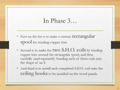
| − | |Let's Build the S.H.O. Drive! - Slide 054 of 176.png||'''In Phase 3…'''<br>• First on the list is to make a custom rectangular spool for winding copper wire.<br>• Second is to make the two S.H.O. coils by winding copper wire around the rectangular spool, and then carefully (and separately) bending each of these coils into the shape of an S.<br>• And third is to install each completed S.H.O. coil onto the ceiling hooks to be installed on the wood panels.
| + | |
| − | |Let's Build the S.H.O. Drive! - Slide 055 of 176.png||'''Magnet Wires'''<br>''(Phase 3 Parts)''<br>• The coils will be made out of a pair of copper wire spools I purchased from Tech-Fixx through Ebay.com designed for use in electromagnets.<br>• These are known as magnet wires.
| + | |
| − | |Let's Build the S.H.O. Drive! - Slide 056 of 176.png||'''Magnet Wires'''<br>''(Phase 3 Parts)''<br>• These are size 12 gauge on the American Wire Gauge scale. Each coil has approximately 100 feet (or 30 meters) of wire, and together they will form a ½” (or 13 mm) thick bundle of copper with a combined resistance of approximately 0.3 ohms, or less than 1/3rd of an ohm.<br>• These Essex Soderon 155 wires have a temperature rating of 311 degrees Fahrenheit or 155 degrees Centigrade.
| + | |
| − | |Let's Build the S.H.O. Drive! - Slide 057 of 176.png||'''Hole Diameter'''<br>''(Compatibility)''<br>• The magnet wire came with spools whose hole diameter fits well with a 5/8” diameter threaded rod, which in turn can also fit holes in the Black & Decker WM125 Workmate. So I will use this to my advantage when unwinding these spools.
| + | |
| − | |Let's Build the S.H.O. Drive! - Slide 058 of 176.png||'''S.H.O. Drive'''<br>''(Design)''<br>• Unlike any other drive motor in on the market today, the S.H.O. Drive will possess a pair of rectangular conductive windings each folded in such a way to look like the letter S, the letter H, or the letter O, depending how on viewed.
| + | |
| − | |Let's Build the S.H.O. Drive! - Slide 059 of 176.png||'''Custom Spool'''<br>''(Assembly)''<br>• Each copper spool will be wound into a rectangle winding with inside dimensions of 24” by 2¼” (or 610 mm by 57 mm).<br>• Then each winding will be carefully folded into the final form of the S.H.O. coil.<br>• Since a spool of these dimensions will be very hard to find on the market, if it exists at all, I will have to make it custom.
| + | |
| − | |Let's Build the S.H.O. Drive! - Slide 060 of 176.png||'''Mailing Tube'''<br>''(Equipment)''<br>• The spool will be made out of a 25” (or about 635 mm) long section of a cardboard mailing tube. Pairs of notches ½” (or about 13 mm) deep will be cut into each end, and the wire will be wound through the resulting 24” by 2¼” (or about 610 mm by 57 mm) inner perimeter.<br>• The tube originally contained square acrylic tubes I ordered from Plastic-Craft (Phase 7).
| + | |
| − | |Let's Build the S.H.O. Drive! - Slide 061 of 176.png||'''Nylon Fasteners'''<br>''(Phase 3 Tools)''<br>• To keep the copper winding bundle tight when curving it to the desired S-curve, several Hillman 3/8" Nylon Cable Clamps from Lowes will be fastened temporarily on the bundle using Hillman Nylon 10-24 Wingnuts and Screws also from Lowe’s.
| + | |
| − | |Let's Build the S.H.O. Drive! - Slide 062 of 176.png||'''Curved Ruler'''<br>''(Tools)''<br>• I must ensure that the long side of the 24”x2¼” conductive winding has the correct form of S curve.<br>• So I will be using a 24”(or 610 mm) Flexible Curved Ruler by Staedtler that I purchased from inside an Artist & Craftsman Supply store.
| + | |
| − | |Let's Build the S.H.O. Drive! - Slide 063 of 176.png||'''S.H.O. Coils'''<br>''(Assembly)''<br>• The two S.H.O. Coils will be spread apart at the middle section of the S curve to make space for the shaft in between.
| + | |
| − | |Let's Build the S.H.O. Drive! - Slide 064 of 176.png||'''Curved Ruler'''<br>''(Tools)''<br>• The 12 American Wire Gauge copper wire is significantly rigid by itself, and it will be even more so when approximately 22 turns of such wire are bundled together in each S.H.O. coil<br>• Therefore I have used the 24” (or 610 mm) Flexible Curved Ruler by Staedtler, which is stiff in its own right, to trace various models for the S Curve of the S.H.O. Coils.
| + | |
| − | |Let's Build the S.H.O. Drive! - Slide 065 of 176.png||'''Visualis Electromagnetism'''<br>''(Software)''<br>• To digitally render the optimized shape for the S.H.O. coils, I used Microsoft Excel to overlay an XY plot chart over a scan of a desired model for the S Curve and adjusted the X and Y values to match the curve.<br>• Then using Excel Functions, I produced the code for a<br>•.viz file which I imported into Visualis Electromagnetism (from visualis-physics.com).
| + | |
| − | |Let's Build the S.H.O. Drive! - Slide 066 of 176.png||'''Tubing Bender'''<br>''(Phase 3 Tools)''<br>• To form the S curves of the S.H.O. Coils, I will use a 1/4”-3/8” Tubing Bender by Pittsburgh from Harbor Freight Tools.
| + | |
| − | |Let's Build the S.H.O. Drive! - Slide 067 of 176.png||'''Tubing Bender'''<br>''(Phase 3 Tools)''<br>• To hold the tubing bender to the workbench, I will use 3 in. Industrial C-Clamps that I obtained from a Harbor Freight Tools store.
| + | |
| − | |Let's Build the S.H.O. Drive! - Slide 068 of 176.png||'''Ceiling Hooks'''<br>''(Phase 3 Parts)''<br>• To hold the winding into the desired configuration, I purchased 7/8” vinyl-coated ceiling hooks from Arrow Hardware through Amazon.com.<br>• These hooks are about the right size to hold each winding separately. They can also be turned as needed to conform to the S curves of the S.H.O. coils.
| + | |
| − | |Let's Build the S.H.O. Drive! - Slide 069 of 176.png||'''Wood Panels'''<br>''(Disassembly)''<br>• Before I can drill pilot holes onto the wood panels for the ceiling hooks, I must unscrew the hinges from the wood panels, set aside the wood base blocks, and then pull out the panels off the bearings.
| + | |
| − | |Let's Build the S.H.O. Drive! - Slide 070 of 176.png||'''Ceiling hooks'''<br>''(Assembly)''<br>• To drill pilot holes for the ceiling hooks, I will again use the 18 Volt Cordless 3/8 in. Drill by Drill Master that I purchased inside a Harbor Freight Tools store.
| + | |
| − | |Let's Build the S.H.O. Drive! - Slide 071 of 176.png||'''Bundle Diameter'''<br>''(Compatibility)''<br>• Each of the two S.H.O. Coils should have a bundled cross-section of about 3/8” inch (or 10 mm) in diameter consisting of approximately 22 turns of 12 American Wire Gauge (or 2 mm diameter) wire.<br>• The openings in the ceiling hooks are 1/3” (or 8 mm) across. Therefore, the coils will be securely held into place by the hooks.
| + | |
| − | |Let's Build the S.H.O. Drive! - Slide 072 of 176.png||'''Electrical Tape'''<br>''(Parts)''<br>• To provide an additional electrical barrier and thermal protection between the windings and the hooks, I will be using Scotch Professional Grade 35 Red Vinyl Electrical Tape that I purchased at Lowe’s.
| + | |
| − | |Let's Build the S.H.O. Drive! - Slide 073 of 176.png||'''Drill Bits'''<br>''(Phase 3 Tools)''<br>• I have purchased a set of 7/64 in. Titanium Nitride High Speed Steel Drill Bits by Warrior from Harbor Freight Tools.<br>• These will allow to me drill pilot holes into the wood panels for the ceiling hooks.
| + | |
| − | |Let's Build the S.H.O. Drive! - Slide 074 of 176.png||'''S.H.O. Coils'''<br>''(Assembly)''<br>• After I make the S.H.O coils and install the ceiling hooks, I will slide the wood panels back on the bearings, and then screw them back onto the base hinges.<br>• Then I will insert the S.H.O. Coils into the ceiling hooks.
| + | |
| − | |Let's Build the S.H.O. Drive! - Slide 075 of 176.png||'''Wire Connector & Sandpaper'''<br>''(Phase 3 Parts & Tools)''<br>• In order to connect the coils together in series, I will be using Utilitech Plastic Standard Wire Connectors (Item no. 48630) and 3M 600 Grit sandpaper from Lowe’s.
| + | |
| − | }} | + | |
| − | <div style="clear:both"></div>
| + | |
| − | ==Phase 4==
| + | |
| − | {{Gallery | + | |
| − | |width=360
| + | |
| − | |align=center
| + | |
| − | |lines=10
| + | |
| − | |footer=
| + | |
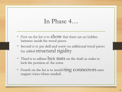
| − | |Let's Build the S.H.O. Drive! - Slide 076 of 176.png||'''In Phase 4…'''<br>• First on the list is to show that there are no hidden batteries inside the wood pieces.<br>• Second is to pre-drill and screw on additional wood pieces for added structural rigidity.<br>• Third is to adhere hex nuts on the shaft in order to lock the position of the rotor.<br>• Fourth on the list is to install ring connectors onto magnet wires where needed.
| + | |
| − | |Let's Build the S.H.O. Drive! - Slide 077 of 176.png||'''In Phase 4…'''<br>• Fifth is to screw the ring connectors on the toggle switch and secure the switch to the base with a mounting adhesive.<br>• Sixth is to install the fan blades on the shaft.<br>• Seventh is to run the S.H.O. Drive and measure the resistance, inductance, as well as the operational ampere current, rotational speed, temperature, and wind speed.
| + | |
| − | |Let's Build the S.H.O. Drive! - Slide 078 of 176.png||'''Transparency'''<br>''(Protocols)''<br>• Before I finish assembly and run some tests, to show that there are no hidden batteries inside the structural wood of the S.H.O. Drive, I will remove the wood and use a metal detector to show that there is no hidden battery. Then after that is established, I will reinstall the wood pieces back on.
| + | |
| − | |Let's Build the S.H.O. Drive! - Slide 079 of 176.png||'''S.H.O. Coils'''<br>''(Disassembly)''<br>• Before I can remove the wood panels, I need to first pull out the S.H.O. Coils from the installed ceiling hooks so that I can separate the panels from each other.
| + | |
| − | |Let's Build the S.H.O. Drive! - Slide 080 of 176.png||'''Wood Panels'''<br>''(Disassembly)''<br>• After the coils are removed, I then have to detach the wood panels from the base blocks by disconnecting the screws and hinges. For this I will use pieces from the iWork 53 piece Tool Set by Olympia Tools.<br>• The ceiling hooks can be unscrewed by hand.
| + | |
| − | |Let's Build the S.H.O. Drive! - Slide 081 of 176.png||'''Metal Detector'''<br>''(Measuring Devices)''<br>• In order to show that there are no hidden batteries inside the S.H.O. Drive wood pieces, I will use the GoerTek Portable Security Scanner that I purchased from GoerTek via Amazon.com
| + | |
| − | |Let's Build the S.H.O. Drive! - Slide 082 of 176.png||'''Metal Spring Clamps'''<br>''(Recap)''<br>• In Phase 1, in order to hold the wood pieces for pre-drilling, I used the Bessey XM7 3-Inch Metal Spring Clamps that I purchased from Woodcraft.<br>• I will use this again to conduct further pre-drilling for some additional structural reinforcements.
| + | |
| − | |Let's Build the S.H.O. Drive! - Slide 083 of 176.png||'''Compact Power Drill'''<br>''(Recap)''<br>• In Phase 1, I pre-drilled holes for the brass screws using the 18 Volt Cordless 3/8 in. Drill by Drill Master from Harbor Freight Tools.
| + | |
| − | |Let's Build the S.H.O. Drive! - Slide 084 of 176.png||'''Drill Bits'''<br>''(Recap)''<br>• In Phase 1, for drilling pilot holes for the brass screws, I used 3/32 in. Titanium Nitride High Speed Steel Drill Bits by Warrior from Harbor Freight Tools.
| + | |
| − | |Let's Build the S.H.O. Drive! - Slide 085 of 176.png||'''Spacers'''<br>''(Phase 4 Parts)''<br>• To ensure that the bearings stay inside the holes, I will screw in HighPoint Solid Brass Screws that I purchased from Woodcraft (after pre-drilling first) to attach very small spacers over the bearing holes. The spacers came with the Birdhouse kits.
| + | |
| − | |Let's Build the S.H.O. Drive! - Slide 086 of 176.png||'''Wide “Wood Shingle”'''<br>''(Phase 4 Parts)''<br>• The length of the two ash wood base blocks differ by 1/8”, so I will pre-drill through a “wide wood shingle” onto the end of one of the base blocks, and then I will screw in additional brass screws in order to secure the wide “wood shingle” into place.
| + | |
| − | |Let's Build the S.H.O. Drive! - Slide 087 of 176.png||'''X-Acto Knife'''<br>''(Phase 4 Tools)''<br>• In order to trim off the excess wood of the wide “wood shingle”, I will use an X-Acto Knife No. 1 with Cap that I purchased from an Artist & Craftsman Supply store.
| + | |
| − | |Let's Build the S.H.O. Drive! - Slide 088 of 176.png||'''Narrow “Wood Shingles”'''<br>''(Parts)''<br>• Additional brass screws will be used to secure two narrow “wood shingles” between each end of the two base blocks to lock them at a 45 degree tilt at both sides.
| + | |
| − | |Let's Build the S.H.O. Drive! - Slide 089 of 176.png||'''#ShoDrives<br>@ShoDrives<br>Sho.wiki''' - ''Drive Replication and Collaboration Site''<br>'''YouTube.com/c/ShoWiki''' - ''Watch and Subscribe Site''<br>'''Facebook.com/ShoDrives''' - ''Like, Share, and Fan Site''
| + | |
| − | |Let's Build the S.H.O. Drive! - Slide 090 of 176.png||'''S.H.O. Drive'''<br>''(Reassembly)''<br>• After the test with the metal detector and installing extra wood pieces, I will remove the “narrow shingles”, reinstall onto the wood panels the ceiling hooks, hinges, shaft, “narrow shingles”, and finally the two S.H.O. coils.
| + | |
| − | |Let's Build the S.H.O. Drive! - Slide 091 of 176.png||'''Hex Nuts'''<br>''(Parts)''<br>• I will secure the shaft with half-a-thread’s worth of special-purpose glue called Loctite Threadlocker Blue 242, which I purchased at Lowe’s.<br>• This will hold hex nuts on the shaft adjacent to the outer facings of the bearings.
| + | |
| − | |Let's Build the S.H.O. Drive! - Slide 092 of 176.png||'''Terminal Rings'''<br>''(Phase 4 Parts)''<br>• To connect the magnet wires onto the toggle switch, I will install 10-106 Terminal Rings from Gardner Bender, which I purchased from Amazon.com.<br>• I will crimp these onto the ends of the magnet wire and screw them onto the toggle switch terminals.
| + | |
| − | |Let's Build the S.H.O. Drive! - Slide 093 of 176.png||'''Sandpaper'''<br>''(Tools)''<br>• To maximize the connection between the terminal rings and the magnet wire, I will sand off the enamel layer at the ends of the wire using 3M 600 Grit sandpaper that I purchased from Lowe’s.
| + | |
| − | |Let's Build the S.H.O. Drive! - Slide 094 of 176.png||'''Crimper Tool'''<br>''(Phase 4 Tools)''<br>• Using the VISE-GRIP Multi Tool Stripper, Cutter and Crimper that I purchased from IRWIN Tools through Amazon.com, I will crimp the ring connector sleeves on the ends of magnet wires.
| + | |
| − | |Let's Build the S.H.O. Drive! - Slide 095 of 176.png||''' Toggle Switch'''<br>''(Phase 4 Parts)''<br>• The ring connectors will then be screwed onto a 20A toggle switch.<br>• This is a double-pole, double-throw switch, or DPDT for short.
| + | |
| − | |Let's Build the S.H.O. Drive! - Slide 096 of 176.png||'''Terminal Rings'''<br>''(Assembly)''<br>• To tighten the screws that will hold the terminal rings onto the toggle switch. I will again use pieces from the iWork 53 piece Tool Set by Olympia Tools.
| + | |
| − | |Let's Build the S.H.O. Drive! - Slide 097 of 176.png||'''ON/OFF Settings'''<br>''(Operation)''<br>• The DPDT (or double-pole double-throw) switch, purchased from TOOGOO through Amazon.com, has one OFF setting and two ON settings.
| + | |
| − | |Let's Build the S.H.O. Drive! - Slide 098 of 176.png||'''OFF Setting'''<br>''(Operation)''<br>• When the OFF setting is selected, the S.H.O. coil will be an open circuit.<br>• The two middle terminals or “poles” matching the OFF setting will be connected to the ends of the coil, but nothing else.
| + | |
| − | |Let's Build the S.H.O. Drive! - Slide 099 of 176.png||'''On Setting #1'''<br>''(Operation)''<br>• When ON setting #1 is selected, it will simply close the circuit.<br>• The two terminals or “poles” for this setting will be connected together with magnet wire.
| + | |
| − | |Let's Build the S.H.O. Drive! - Slide 100 of 176.png||'''On Setting #2'''<br>''(Operation)''<br>• ON setting #2, when selected, may be used to connect the coil to a Sinometer VC6243+ LC meter in series with the coils.<br>• This will be used to measure the Inductance of the S.H.O. Coil Winding.
| + | |
| − | |Let's Build the S.H.O. Drive! - Slide 101 of 176.png||'''LC meter'''<br>''(Measuring Devices)''<br>• I purchased the Sinometer VC6243+ LC meter from Sinometer via Amazon.com
| + | |
| − | |Let's Build the S.H.O. Drive! - Slide 102 of 176.png||'''LC meter'''<br>''(Measuring Devices)''<br>• The Sinometer VC6243+ LC meter can measure:<br>• Magnetic Inductance <br>''(represented by L)''<br>• Electrical Capacitance <br>''(represented by C)''
| + | |
| − | |Let's Build the S.H.O. Drive! - Slide 103 of 176.png||'''On Setting #2'''<br>''(Operation)''<br>• ON setting #2 may also be used to connect the coil to a Vichy VC480C+ Digital Milli-ohm Meter.<br>• This will be used to measure the Resistance of the S.H.O. Coil Winding.
| + | |
| − | |Let's Build the S.H.O. Drive! - Slide 104 of 176.png||'''Milli-ohm Meter'''<br>''(Measuring Devices)''<br>• I purchased the Vichy VC480C+ Digital Milli-ohm Meter from modders_chn via eBay.com
| + | |
| − | |Let's Build the S.H.O. Drive! - Slide 105 of 176.png||'''Milli-ohm Meter'''<br>''(Measuring Devices)''<br>• The Vichy VC480C+ Digital Milli-ohm Meter uses the 4-wire method of measuring very small resistances.<br>• The 4-wire method involves passing a current through a resistor and measuring the voltage across the terminals.
| + | |
| − | |Let's Build the S.H.O. Drive! - Slide 106 of 176.png||'''On Setting #2'''<br>''(Operation)''<br>• ON setting #2 may also be used to connect the coil to an Extech 411 True-RMS Multimeter.<br>• This will be used to measure the current of the S.H.O. Coil Winding.
| + | |
| − | |Let's Build the S.H.O. Drive! - Slide 107 of 176.png||'''True-RMS Multimeter'''<br>''(Measuring Devices)''<br>• I purchased the Extech 411 True-RMS Multimeter from Fry’s Electronics.
| + | |
| − | |Let's Build the S.H.O. Drive! - Slide 108 of 176.png||'''True-RMS Multimeter'''<br>''(Measuring Devices)''<br>• The Extech 411 True-RMS Multimeter will be used calculate the root mean square or RMS of the current & voltage.
| + | |
| − | |Let's Build the S.H.O. Drive! - Slide 109 of 176.png||'''True-RMS Multimeter'''<br>''(Measuring Devices)''<br>• The heat loss in the winding can be calculated by taking the product of winding resistance and the mean square current.
| + | |
| − | |Let's Build the S.H.O. Drive! - Slide 110 of 176.png||'''True-RMS Multimeter'''<br>''(Measuring Devices)''<br>• This device does not measure the phase difference between current and voltage.<br>• Therefore, it cannot be used to measure power in a circuit with an inductor, capacitor, or other circuit components which may cause a phase difference between current and voltage.<br>• However, this meter can be used to calculate heat losses and measure induced voltage.
| + | |
| − | |Let's Build the S.H.O. Drive! - Slide 111 of 176.png||'''Mounting the Switch'''<br>''(Assembly)''<br>• 3M Scotch Heavy Duty Mounting Tape (½” (or 13mm) wide) will be used to mount the toggle switch onto the rear “narrow shingle”.
| + | |
| − | |Let's Build the S.H.O. Drive! - Slide 112 of 176.png||'''Alligator Clip Leads'''<br>''(Equipment)''<br>• For better lead connections to On Setting #2, I purchased Heavy Duty 12 AWG - 3 Feet Long DC Power Supply Leads from PS-Mastech via Amazon.com.
| + | |
| − | |Let's Build the S.H.O. Drive! - Slide 113 of 176.png||'''Alligator Clip Leads'''<br>''(Equipment)''<br>• These leads have a wire size identical to the wire used in the S.H.O. Coil and therefore support a similar amount of current. These leads are gauge 12 on the American Wire Gauge scale.<br>• At one end, they have banana plugs which may be connected to the multimeters which I will be using.<br>• At the other end, these leads have alligator clips which can attach to the toggle switch at On Setting #2.
| + | |
| − | |Let's Build the S.H.O. Drive! - Slide 114 of 176.png||'''Output Demonstration'''<br>''(Protocols)''<br>• One key task is to absorb and demonstrate the mechanical output of the S.H.O. Drive.<br>• To do this demonstration, I will use a propeller, which will transfer out mechanical energy to air, producing wind.
| + | |
| − | |Let's Build the S.H.O. Drive! - Slide 115 of 176.png||'''Fan Blades'''<br>''(Phase 4 Parts)''<br>• This Automotive cooling fan has 5 blades and has a diameter of 12” (or about 30 cm).<br>• I purchased this item from Flex-a-Lite through Amazon.com <br>• It’s part number 1312.
| + | |
| − | |Let's Build the S.H.O. Drive! - Slide 116 of 176.png||'''Washers and Hex Nuts'''<br>''(Parts)''<br>• I will secure the 12” (or 30 cm) diameter fan with its 5/8” (or 16 mm) bore hole, through the 5/8” (or 16 mm) diameter rod by compressing it between a pair of zinc-plated washers that I purchased at Lowe’s and a pair of zinc-plated hex nuts that I purchased at Tacoma Screw.
| + | |
| − | |Let's Build the S.H.O. Drive! - Slide 117 of 176.png||'''Adjustable Wrench'''<br>''(Phase 4 Tools)''<br>• To tighten the hex nuts against the washers and the propeller, I purchased a Kobalt 8-in (about 200 mm) Chrome Vanadium Steel Adjustable Wrench from Lowe’s.
| + | |
| − | |Let's Build the S.H.O. Drive! - Slide 118 of 176.png||'''Tachometer'''<br>''(Measuring Devices)''<br>• To measure rotation speed, I will use the AGPtek Professional Digital Laser Photo Tachometer that I purchased from AGPtek through Amazon.com
| + | |
| − | |Let's Build the S.H.O. Drive! - Slide 119 of 176.png||'''Tachometer'''<br>''(Tools)''<br>• To properly use the AGPtek Professional Digital Laser Photo Tachometer, I must use the reflective tape that was included with the kit.<br>• This included reflective tape is designed to allow photo tachometers to accurately measure rotational speed.
| + | |
| − | |Let's Build the S.H.O. Drive! - Slide 120 of 176.png||'''Compact Disc'''<br>''(Compatibility)''<br>• I will apply the reflective tape onto the label side of a CD, which I will then insert over the 5/8” diameter threaded rod.<br>• The diameter of the CD’s center hole is 15mm. As a result, if you take the depth of the threads into account, the CD should hold steady without modifying it.<br>• The CD will be secured onto the shaft with hex nuts.
| + | |
| − | |Let's Build the S.H.O. Drive! - Slide 121 of 176.png||'''Plastic Furniture Tips'''<br>''(Phase 4 Parts)''<br>• To prevent the ends of the shaft from damaging things, I will cover them with 5/8” (or 16 mm) Black Plastic Furniture Tips from the Hillman Group that I purchased at Lowe’s.
| + | |
| − | |Let's Build the S.H.O. Drive! - Slide 122 of 176.png||'''Electrical Tape'''<br>''(Parts)''<br>• In order to form a tight grip between the shaft and the Plastic Furniture Tips, I will use the Scotch Professional Grade 35 Red Vinyl Electrical Tape, also from Lowe’s.
| + | |
| − | |Let's Build the S.H.O. Drive! - Slide 123 of 176.png||'''Electrical Resistance'''<br>''(Pre-run Testing)''<br>• To measure the electrical resistance of the S.H.O. Winding, I will be using the Vichy VC480C+ Digital Milli-ohm Meter.
| + | |
| − | |Let's Build the S.H.O. Drive! - Slide 124 of 176.png||'''Magnetic Inductance'''<br>''(Pre-run Testing)''<br>• To measure the magnetic inductance of the S.H.O. Winding as a function of rotor position, I will use the Sinometer VC6243+ LC meter.
| + | |
| − | |Let's Build the S.H.O. Drive! - Slide 125 of 176.png||'''Induced Voltage vs. Rotation'''<br>''(Pre-run Testing)''<br>• Using the Extech 411 RMS Multimeter and the AGPtek Professional Digital Laser Photo Tachometer, I will measure the root mean square value of the induced voltage as a function of rotation speed.
| + | |
| − | |Let's Build the S.H.O. Drive! - Slide 126 of 176.png||'''Electric Current'''<br>''(Run Testing)''<br>• During the test run, I will use the Extech 411 RMS Multimeter to measure the root mean square value of the induced current.
| + | |
| − | |Let's Build the S.H.O. Drive! - Slide 127 of 176.png||'''Thermometer'''<br>''(Tools)''<br>• To measure the temperature of the coil, I will use the DTQ450X Quick-Read Thermometer from CDN that I purchased through Amazon.com<br>• This thermometer has a range of -40° F to +450° F (or -40° C to +230° C)
| + | |
| − | |Let's Build the S.H.O. Drive! - Slide 128 of 176.png||'''Thermometer Accuracy'''<br>''(Pre-run Testing)''<br>• I must test the thermometer to see if it takes accurate readings<br>• First, I will test the temperature of the air near the drive motor.<br>• Then, after sanitizing the thermometer with 70% isopropyl alcohol wipes, I will test the temperature under my tongue, which should be about 98.6 degrees Fahrenheit or 37 degrees Centigrade.
| + | |
| − | |Let's Build the S.H.O. Drive! - Slide 129 of 176.png||'''Before Temperature'''<br>''(Pre-run Testing)''<br>• After sanitizing the thermometer, I will insert the thermometer into one of the flat sections of the S.H.O. Drive Winding. I will also test the other three flat sections.<br>• I will take out the thermometer out during the duration test, and I will set up water and ice samples to test the thermometer with, again sanitizing between measurements.
| + | |
| − | |Let's Build the S.H.O. Drive! - Slide 130 of 176.png||'''Duration Run'''<br>''(Run Testing)''<br>• I will test a duration run of the drive motor. In this test, I will measure the S.H.O. Drive’s:<br>• Root mean square current<br>• Wind Speed<br>• Air Temperature<br>• Coil Temperature<br>• Rotational Speed
| + | |
| − | |Let's Build the S.H.O. Drive! - Slide 131 of 176.png||'''Anemometer'''<br>''(Measuring Equipment)''<br>• During the test run, I will measure the air speed in front and rear of the S.H.O. Drive fan, using the OriGlam Digital Anemometer & Thermometer from OriGlam that I purchased through Amazon.com<br>• This anemometer can measure winds between 196 and 4900 ft/min (2.2 and 56 mph) (3.6 and 90 kph).
| + | |
| − | |Let's Build the S.H.O. Drive! - Slide 132 of 176.png||'''After Temperature'''<br>''(Post-Run Testing)''<br>• After the duration test, I will reinsert the thermometer into the S.H.O. Drive Winding into the same sections tested previously, again, sanitizing between measurements.
| + | |
| − | }} | + | |
| − | <div style="clear:both"></div>
| + | |
| − | ==Phase 5==
| + | |
| − | {{Gallery
| + | |
| − | |width=360
| + | |
| − | |align=center
| + | |
| − | |lines=10
| + | |
| − | |footer=
| + | |
| − | }}
| + | |
| − | <div style="clear:both"></div>
| + | |
| − | ==Phase 6==
| + | |
| − | {{Gallery
| + | |
| − | |width=360
| + | |
| − | |align=center
| + | |
| − | |lines=10
| + | |
| − | |footer=
| + | |
| − | }}
| + | |
| − | <div style="clear:both"></div>
| + | |
| − | ==Phase 7==
| + | |
| − | {{Gallery
| + | |
| − | |width=360
| + | |
| − | |align=center
| + | |
| − | |lines=10
| + | |
| − | |footer=
| + | |
| − | }}
| + | |
| − | <div style="clear:both"></div>
| + | |
| − | </center>
| + | |
